
10 led VU Meter using LM3915
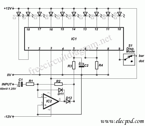
The described circuit operates on a principle of visual signal representation using a VU meter configuration. The core component, the LM3915, is a dot/bar graph display driver that can illuminate up to 10 LEDs in response to an input voltage. This IC is particularly suited for audio level indication, providing a clear visual representation of signal strength.
The circuit begins with the input signal, which is fed into the TL071 operational amplifier. This op-amp is configured for half-wave rectification, ensuring that only the positive half of the input waveform is processed. This rectified output is then fed into the LM3915, which interprets the voltage level and activates the corresponding number of LEDs based on the input signal strength.
The switch S1 introduces versatility to the circuit by allowing users to select different voltage ranges for indication. This feature is essential for applications where varying signal levels need to be monitored. The circuit can effectively display levels from as low as 60 mV, suitable for low-level audio signals, up to 25 V, accommodating higher voltage signals.
In terms of component selection, the TL071 is favored for its low noise and high precision, making it ideal for audio applications. The LM3915's ability to drive multiple LEDs without additional components simplifies the design and reduces potential points of failure.
Overall, this circuit design provides a reliable and visually intuitive method for monitoring signal levels, making it suitable for various electronic applications, including audio equipment, signal processing, and general voltage level monitoring.Circuit diagram is a very simple circuit-level indication, with 10 Led. Used a series of half-wave rectification of precision around IC2 TL071, with a single. LM3915 IC is used to control the led, as an indicator VU Meter. LM3915 can be controlled 10 led. With the switch S1, we can choose an indication from the LED. Level mV into a 60-1st, 25 V. T he following is a schematic drawing:
Related Circuits
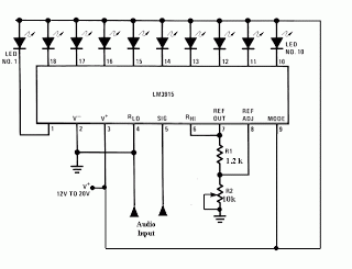 Audio Level Meter Circuit LM3915
This meter circuit uses just one IC and a very few number of external components. It displays the audio level in terms of 10 LEDs. The input voltage can vary from 12V to 20V, but suggested voltage is 12V. The LM3915 is a monolithic integrated circuit that senses analog voltage...
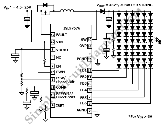 LED Driver: 6 Channels with Phase Shift Control
We can use ISL97676 as a LED driver that drives 6 channels of LED current for TFT-Display. The ISL97676 is used to drive 6 channels of LED to support 78 LEDs from 4.5V to 26V or 48 LEDs from a boost supply of 2.7V to 26V and a separate 5V...
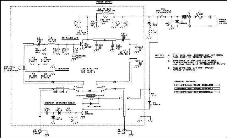 The FARA 2 meter amplifier project
This article describes a 2 meter amplifier capable of running 25-30 watts output. More than 35 amplifiers have been procured at a cost of less than $50 each in these quantities. Photo A shows the final version of the circuit board; the completed amplifier is shown in Photo B. It...
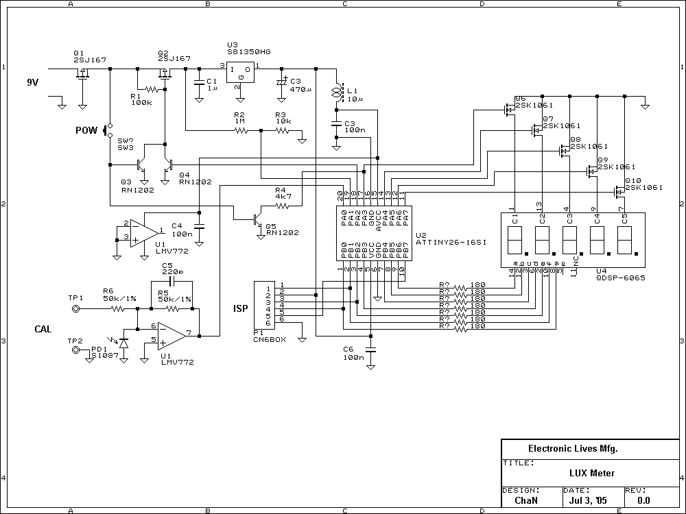 Lux meters attiny26-16 light measurement circuit
Lux meter circuit atmel attiny26-16 microcontroller based on the value of the LED displays on the display lux with LEDs placed on 2sk1061 MOS.
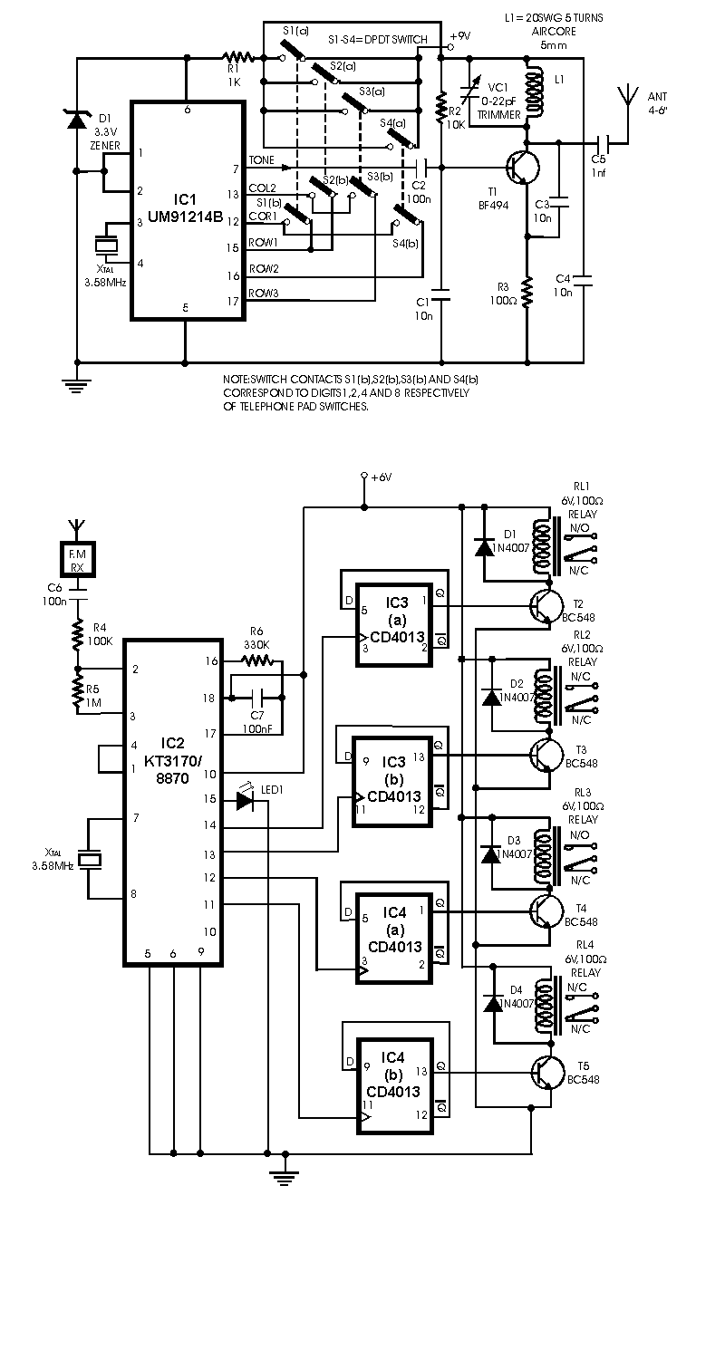 Radio Remote Control using DTMF
Radio Remote Control using DTMF. Here is a circuit of a remote control unit which makes use of the radio frequency signals to control various electrical appliances. This remote control unit has.