
The FARA 2 meter amplifier project

The 2-meter amplifier circuit is designed to provide reliable performance in VHF applications. It utilizes the MRF1946A, which is known for its high gain and efficiency, making it suitable for amateur radio and other communication purposes. The design incorporates essential components for stability and protection, such as the reverse polarity diode and fuse, ensuring that the amplifier can withstand accidental misconfigurations without damage.
The decoupling capacitors and inductors play a crucial role in maintaining signal integrity by filtering out noise from the power supply. The output stripline and capacitor adjustments are critical for optimizing performance at the desired frequency of 146 MHz, ensuring that the amplifier operates efficiently within its intended parameters.
The inclusion of a low-pass filter enhances the amplifier's ability to reject unwanted harmonics, which is vital for compliance with regulatory standards and minimizing interference with other communication signals. The resistive input attenuator allows for flexibility in interfacing with various transceiver models, accommodating both older and newer devices.
Overall, this amplifier design exemplifies a well-thought-out approach to VHF amplification, balancing cost, performance, and educational value for those engaged in amateur radio construction and experimentation. The provided schematic and component specifications serve as a valuable resource for builders looking to replicate or modify the design for their specific applications.This article describes a 2 meter amplifier capable of running 25-30 watts output. More than 35 amplifiers have been procured at a cost of less than $50 each in these quantities. Photo A shows the final version of the circuit board; the completed amplifier is shown in Photo B. It is designed around one of the newer bipolar RF devices from Motorola, an MRF1946A (Q1). This device compares favorably with many of the RF FETs available as the MRF1946 is capable of developing 10 dB gain at 146 MHz, while the older bipolar devices (the 2N6080 series) produce only about 5. 7 dB gain. RF FETs are generally rated at 13 dB gain at 28 volts-. in the 12-14 volt range they also yield about 10 dB. The design presented here is unconditionally stable, while FET amplifiers require a bias supply and careful tuning at the higher voltages to maintain stability.
The cost of the MRF1946A is only about two-thirds that of the FETS, yielding the most "Bang for the Buck!" Motorola produced an application note (RF Device Data, Application AN955) for a 150 mW to 30 watt land mobile VHF amplifier in the 160 MHz range, based on the MRF1946. This was the starting point for the design. The schematic diagram is shown in Figure 1. DC voltage into the amplifier is decoupled by C2, C3, L1 C4, C5, and L2. D2 is the reverse polarity protection diode-if the voltage is inadvertently reversed, D2 will limit the reverse voltage to 0.
7 volts and fuse F1 will open, protecting the amplifier. The output stripline (Z1) described in the application note was lengthened for operation at 146 MHz and the output capacitor (C10) was empirically adjusted to yield an efficiency in the 70% range, just about what one would expect of a Class-C amplifier. The input circuit was derived from the formulas given in the RSGB VHF/UHF Manual. This manual is highly recommended for those interested in VHF/UHF construction. Similar examples of impedance calculations can be found in several editions of The Radio Amateur`s Handbook.
This approach was intended to demonstrate the microstrip vs. lumped constant techniques for impedance matching as one of the more subtle objectives of the HACKERS group is to provide some informal education on radio construction and design practices. A low pass filter network (C13, C14, L5) is in series with the output to enhance harmonic rejection. Incorporated into the design is a resistive input attenuator network (R2, R3, R4, R5). The RF power transistor (Q1) is intended to be driven with 2 to 3 watts input; higher drive levels will not increase the output substantially.
Most of the older HTs can drive the amplifier directly, but the new breed of high power, 4 to 7 watt HTs will require the input attenuator. When the attenuator is used, the 50 ohm microstrip must be isolated at the 10 ohm resistors. Cut the circuit foil at the locations noted on the parts placement diagram, Figure 2. The attenuator represents a nominal 3 dB loss; that is, half of the power is dissipated in the network.
In addition to limit 🔗 External reference
Related Circuits

A remote sensor transmits data through the mains supply, with a temperature range of 00.0 to 99.9 °C. This circuit is designed for precise centigrade temperature measurement. The circuit employs a remote temperature sensor that communicates its readings over the...
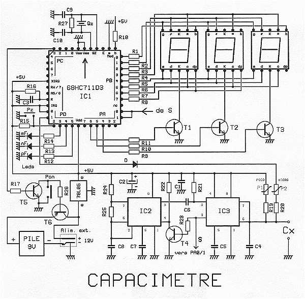
The proposed capacitance is a very powerful assembly to measure in 7 ranges capacitors of 1 pF to 999 uF, with an excellent precision of about 10^-3. The range change is fully automatic. The display shows 3 digits with...
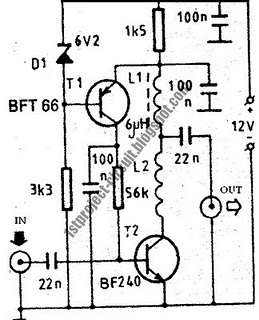
This design presents a simple antenna amplifier electronic circuit project, which can be utilized based on the provided circuit diagram. The antenna amplifier operates effectively within a frequency range of 1 to 300 MHz. It is suitable for high...
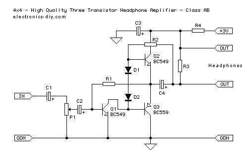
This is an improved version of a headphone amplifier I built many years ago. I wanted to share it because this simple circuit has done great service to me through all these years. It is very simple and reliable,...
This sound level meter serves as an effective one-chip replacement for standard analog meters. It is entirely solid-state, ensuring durability and longevity. The circuit is built around the LM3915 audio level integrated circuit (IC) and requires only a minimal...
A vibration meter circuit depicted in the schematic diagram utilizes the LM3915 as the primary active component. This vibration meter employs a piezoelectric sensor. The vibration meter circuit is designed to measure and display vibration levels through a visual output....