
Lux meters attiny26-16 light measurement circuit

The lux meter circuit operates by measuring ambient light levels and converting these measurements into a readable format displayed on an LED array. The Atmel ATtiny26-16 microcontroller serves as the central processing unit, executing the necessary algorithms to interpret the sensor input and control the output display.
In this design, light is detected using a suitable light sensor, which provides an analog voltage proportional to the illumination level. This voltage is fed into one of the analog-to-digital converter (ADC) channels of the ATtiny26-16. The microcontroller processes this analog signal, converting it into a digital value that corresponds to the lux level.
To drive the LED display, the circuit employs 2SK1061 MOSFETs. These MOSFETs are used to handle the current required by the LEDs without overloading the microcontroller's output pins. The microcontroller controls the gate of each MOSFET, allowing it to turn the LEDs on or off based on the computed lux values.
The LED display is configured to show the lux readings in a user-friendly format. This may involve using multiple LEDs to represent different ranges of light intensity, or a more complex arrangement to provide a more precise numerical display.
Additional components in the circuit may include resistors for current limiting, capacitors for filtering, and possibly a power supply circuit to ensure stable operation. The overall design emphasizes efficiency and accuracy in light measurement, making it suitable for various applications where light intensity monitoring is essential.Lux meter circuit atmel attiny26-16 microcontroller based on the value of the LED displays on the display lux with LEDs placed on 2sk1061 MOS. 🔗 External reference
Related Circuits
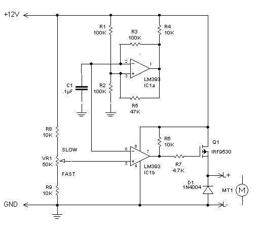
The inquiry pertains to identifying the component within the circuit that regulates the minimum RPM achievable. The current operational range of the motor is between 1400 and 3700 RPM, and there is an interest in modifying the circuit to...
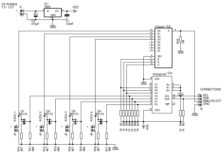
This page describes a battery tester designed to characterize batteries and save the results on a microSD card. The battery tester circuit is engineered to evaluate the performance and capacity of various battery types, providing accurate and reliable data storage...
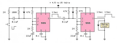
The LM555 timer circuit is similar to the previous design but incorporates two stages, allowing for control over both the pulse width and the delay. The LM555 timer is a versatile integrated circuit widely used in various timer, delay, pulse...
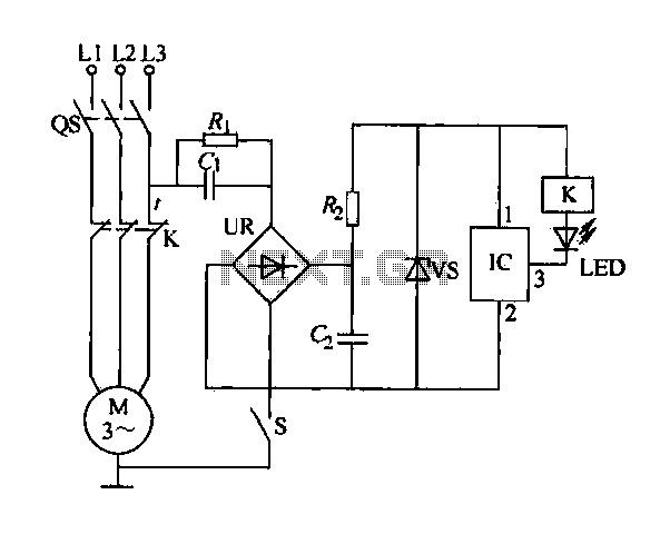
The electric sewing machine saving circuit is designed with a Hall switch integrated circuit (IC) and a relay (K). When the switch is closed, power is activated. The circuit includes a resistor (R) and a capacitor (Ci) for RC...
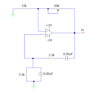
An operational amplifier-based sine wave generator circuit, commonly known as a Wien bridge oscillator, is recognized for its simplicity and stability. The Wien bridge oscillator connects the Wien bridge circuit between the amplifier's input and output terminals. The bridge...

Figure 4-27 (b) line demonstrates a configuration that enhances the output current waveform DC voltage compared to the line in Figure 4-27 (a). This configuration can be utilized for motors with larger capacities. The circuit illustrated in Figure 4-27 (b)...