
10 Mhz QRSS Beacon
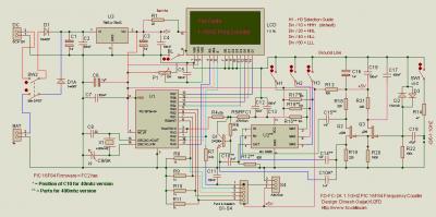
The described beacon circuit employs a Colpitts oscillator configuration, which is known for its stability and simplicity in generating RF signals. The oscillator is tuned to the QRSS frequency of 10140.020 kHz using a quartz crystal, which ensures precise frequency control. The inclusion of a 2N2222A transistor in the power stage allows for efficient amplification of the RF signal, achieving the desired output power of 20 milliwatts.
For filtering, the absence of a low-pass filter in the initial tests indicates a focus on basic functionality, with the Kenwood Antenna Tuner acting as an alternative to manage unwanted harmonics and provide a cleaner output signal. This approach is practical for early-stage testing, allowing for quick adjustments and monitoring of the signal quality.
The NE555 timer circuit serves as a versatile component in this design, generating a pattern for the CW keying. By modulating the output of the oscillator, it produces Morse code signals that can be visually monitored on the ARGO software, which is commonly used for decoding and analyzing weak signals in the QRSS spectrum.
Overall, this beacon design represents a blend of various inspirations and practical engineering choices, showcasing an effective method for amateur radio experimentation in the QRSS domain. The use of readily available components and simple circuitry makes it accessible for hobbyists while providing a platform for further enhancements and refinements in future iterations.My beacon is using now a simple CW keying QRSS3 10140. 020 khz, power is 20 milliwatt. I`m using a PIC program PicBeacon di Ik2pcb. Click here for the reception report The idea of making this beacon start from two project, one is the Hans G0GPL QRSS Junkbox Beacon and the other is the simple "2 transistor" project from Colin G6AVK. Using this two circuit and also looking idea from Alessandro I0SKK Beacon i start the builing with ugly construction (or ground-plane construction) my beacon. Using a simple 10140 khz xtal (Tnx Peter DL6NL !)i build the Colpitts oscillator and the "power" stage with a 2n2222a transistor.
In the first test the "low pass" filter is not used as you can see in the photo, as a "band filter" i`m using Kenwood Antenna Tuner. A simple circuit with NE555 is used as a patten generator, and in the ARGO screen look like a lot of "T" in morse Code.
The frequency is 10140. 020 Khz. 🔗 External reference
Related Circuits
The following circuit illustrates a 40 MHz/400 MHz Frequency Counter Circuit Diagram. This circuit is based on the PIC16F84 IC. Features: The frequency counter circuit operates within the range of 40 MHz to 400 MHz, utilizing the PIC16F84 microcontroller...
NJM2268 is a dual video 6dB amplifier designed for S-VHS VCRs, high-bandwidth VCRs, and similar applications. One channel features a clamp function that stabilizes the DC level of the video signal, while the other channel operates as a bias...
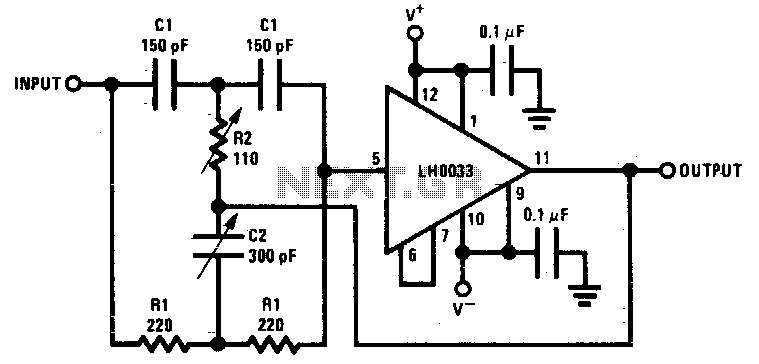
Component value sensitivity is extremely critical, as are temperature coefficients and matching of the components. Best performance is attained when perfectly matched components are used and when the gain of the amplifier is unity. To illustrate, the quality factor...
A 183.6 MHz SAW filter is utilized in a CDMA application. The S-parameter of the SAW filter is employed to simulate the interaction with the mixer. An example is provided using the SAWTEK 855893 SAW filter. This application note...
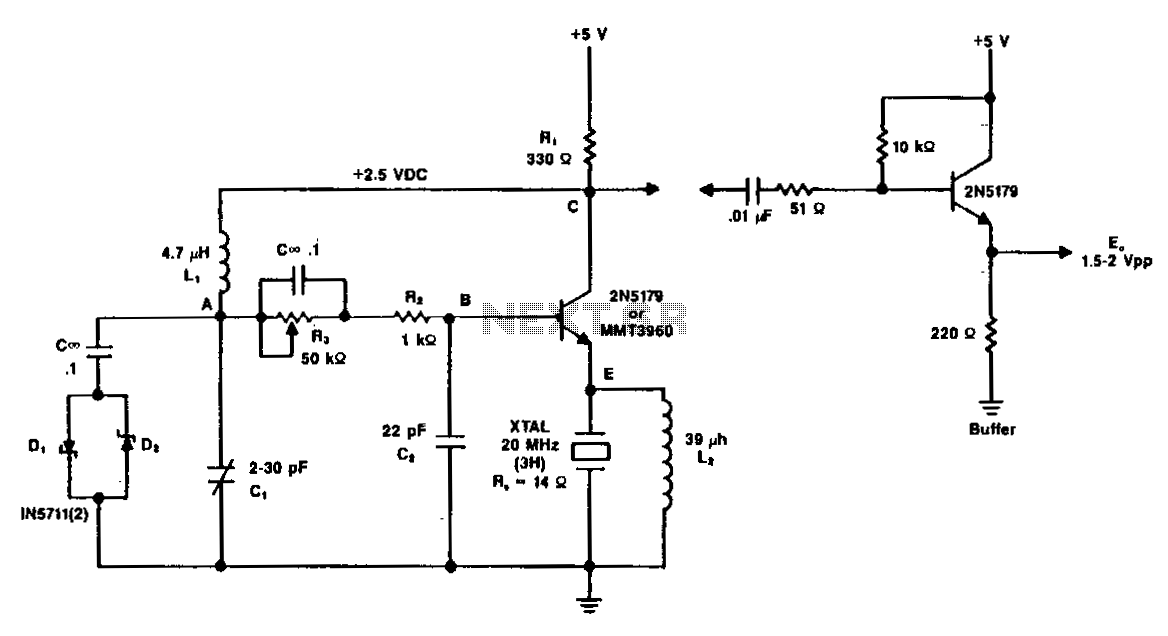
A typical circuit operating at 20 MHz is illustrated. The crystal, featuring an internal series resistance (Rs) of 14 ohms, oscillates at its third harmonic frequency. Diode clamps D1 and D2 ensure constant amplitude control. The transistor functions continuously...
The 555 timer oscillator section can be removed and replaced with a preferred microphone modulating circuit to transmit audio to a television set, requiring minimal tuning. The schematics available on Schematics Depot were sourced from the internet and are...