
hp max2338 mixer if saw filter match at 183 6mhz for cdma

The 183.6 MHz SAW filter serves a critical role in CDMA applications, where precise frequency selection and signal integrity are paramount. The filter's S-parameters, which characterize its response in terms of reflection and transmission coefficients, are essential for simulating the behavior of the filter within the overall circuit. The integration of the SAWTEK 855893 SAW filter into the design necessitates careful consideration of the impedance matching between the filter and the MAX2338 mixer.
The design process begins with establishing the required source differential impedance, which is typically several hundred ohms for an IF SAW filter. The MAX2338 mixer, known for its high performance in CDMA applications, has an optimum load impedance in the range of 2kΩ to 3kΩ, contingent on the IF frequency. This discrepancy between the filter and mixer impedances necessitates the implementation of a high-to-low impedance transformation circuit to achieve optimal matching and performance.
The initial phase of the design involves performing S-parameter simulations using the mixer’s differential equivalent circuit at the target IF frequency. The four-port S-parameter data provided by the SAW filter manufacturer is integrated into the simulation to evaluate the filter's performance without any external matching circuits. This simulation phase allows for the identification of critical parameters such as insertion loss and amplitude ripple, which are crucial for maintaining the integrity of the CDMA signal.
Incorporating real-world PCB characteristics into the simulation enhances the accuracy of the model. Factors such as transmission line lengths, substrate thickness, and dielectric properties must be considered to ensure that the simulated performance closely matches the actual circuit behavior. The correlation between the simulated and measured performance of the MAX2338 mixer gain and the SAW filter insertion loss is a testament to the effectiveness of the initial design efforts.
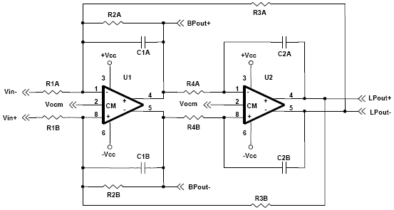
However, it is important to note that the final circuit may require minor adjustments to the component values derived from simulation. These adjustments are necessary to account for any discrepancies arising from unmodeled board characteristics or variations in component tolerances. The overall design process emphasizes the importance of iterative testing and refinement to achieve the desired performance in the final application.183. 6MHz SAW filter in a CDMA application. The SAW filter S-parameter is used to simulate the interface with the mixer. A worked example is provided with a SAWTEK 855893 SAW filter. An optimum impedance matching circuit between the MAX2338 mixer differential IF ports and a 183. 6MHz CDMA IF SAW filter is presented in this application note. A practi cal HP-ADS simulation schematic file along with test measurement results are included. Optimization criteria is based on minimum filter insertion loss, peak-to-peak amplitude ripple, and highest mixer IIP3 performance. Typically, an IF SAW filter wants to see a source differential impedance in the order of several hundred ohms.
The MAX2338 CDMA mixer output trans conductance stage`s optimum load is in the order of 2k © to 3k © as a function of IF frequency. Therefore, a high to low impedance transformation topology is needed for an optimum match. Initial S-parameter linear simulation is performed based on the mixer differential equivalent circuit at the intended IF frequency of operation and the four-port S-parameter of the SAW device (without any external matching circuits) supplied by the SAW manufacturer.
Actual product platform PCB information such as embedded transmission line lengths, substrate thickness, dielectric material, and size characteristics, can all be incorporated in the simulation for accurate modeling. Component values derived from simulation and subsequently implemented on circuit board on the first attempt demonstrated very good correlation between the MAX2338 mixer gain and SAW filter insertion loss.
Final circuit implementation may require slight deviation from simulated component values to account for board that have not been modeled. 🔗 External reference
Related Circuits
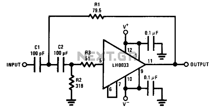
The circuit features a cutoff frequency of 10 MHz. Resistor R3 is utilized to prevent the input capacitance of the amplifier from affecting the filter response at the desired frequency. An equivalent low-pass filter can also be derived through...
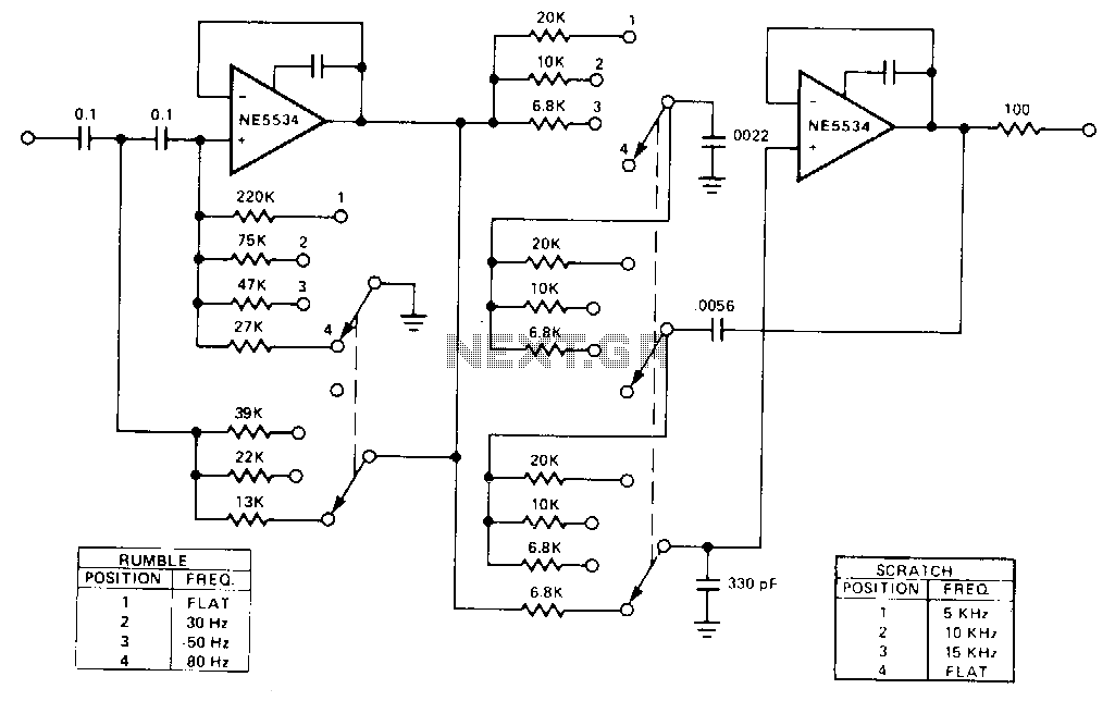
This audio bandpass filter is useful for amplification and filtering of weak AM TV video carriers. For example, a DFM (digital frequency audio multimeter) may have insufficient input sensitivity for measuring extremely weak SSB TV video audio signals. By...

This is a simple low pass filter that can be used at any audio circuitry. It uses the 741 opamp. More: Do not forget to use double power supply of 5 volts. You can use 2 batteries as shown...
This is a variable bandpass amplifier with adjustable low and high-frequency cutoffs. A variable bandpass amplifier is designed to allow a specific range of frequencies to pass through while attenuating frequencies outside this range. The adjustable low and high-frequency cutoffs...
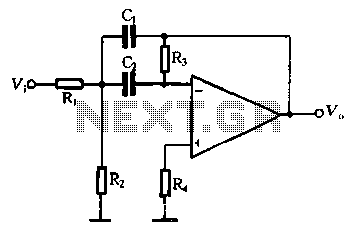
The performance of a second-order band-pass filter is primarily influenced by the quality factor (Q) and the center frequency (Si). To adjust the Q value, R3 should be modified first, followed by adjustments to C0. However, these adjustments will...
A biquad filter is a type of linear filter that implements a transfer function which is the ratio of two quadratic functions. It is available in low pass, high pass, band pass, and notch configurations. A biquad filter is characterized...