
10 SEC SCS TIMER
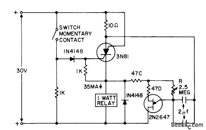
The circuit described utilizes a silicon-controlled switch (SCS) as a key component for controlling power to a relay load and a unijunction transistor (UJT) timing circuit. The operation begins with the activation of the switch, which sends a positive voltage pulse to the gate of the SCS. This pulse is crucial as it triggers the SCS into its conductive state, allowing current to flow through the relay load. The relay load can be any device that requires switching on, such as a motor or a lamp.
The timing aspect of this circuit is governed by an R-C timing circuit, which determines how long the SCS remains in the on state. The resistor (R) and capacitor (C) are configured in such a way that they create a time delay, which is essential for controlling the duration of the pulse sent to the SCS. When the capacitor charges to a certain voltage threshold, the UJT will trigger, and this action will initiate the timing sequence.
Once the predetermined timing interval has elapsed, the UJT timing circuit generates a negative pulse. This pulse is directed to the anode of the SCS, effectively turning it off. The transition from the on state to the off state is critical for ensuring that the relay load is deactivated after the desired operation is completed.
This circuit is particularly useful in applications where precise timing control is necessary, such as in automated systems, timers, and other electronic control applications. The simplicity of the R-C timing circuit combined with the robust switching capability of the SCS makes this design effective for various electronic control tasks.Switch applies positive pulse to gate of scs, triggering it on and thereby supplying power to relay load and ujt timing circuit. At end of timing interval, determined by R-C, timer feeds negative pulse to anode to turn off scs. -"Transistor Manual, " Seventh Edition, General Electric Co. , 1964, p 435. 🔗 External reference
Related Circuits
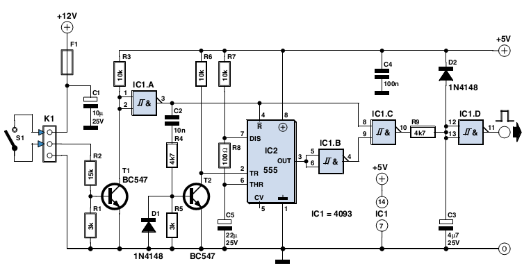
The circuit described here was designed as an addition to a remotely controlled garage door opener. The problem was that a brief burst of interference, arising from a thunderstorm or a mains spike, was enough to trigger the mechanism,...
In this circuit, a 4017 CMOS decade counter can be utilized to construct a timer circuit. The push-button S1 will discharge capacitor C1 through resistor R2. The 4017 CMOS decade counter is a versatile integrated circuit that can count from...
This clock timer utilizes a PIC16F628 microcontroller to display a 3.5-digit time format and control an external load. It is programmable to time intervals from 1 to 59 minutes. The clock features a calendar that accounts for leap years...
Certain circumstances and areas require the detection and securing of entrance paths through alarm systems, ensuring that whenever an individual opens an entrance door, the situation is instantly monitored by triggering an alarm. Battery-operated window and door alarms are...
This circuit provides a visual 9-second delay using 10 LEDs before closing a 12-volt relay. When the reset switch is closed, the 4017 decade counter resets to the 0 count, illuminating the LED driven from pin 3. The 555...
The EUA2032 is a high-efficiency, 2.5W mono class-D audio power amplifier. A newly developed filterless PWM modulation architecture further reduces EMI and THD+N, as well as eliminates the LC output filter, thereby reducing the external component count, system cost,...