
4017 For Flip-Flop Timer

The 4017 CMOS decade counter is a versatile integrated circuit that can count from 0 to 10, providing an output high on one of its ten output pins for each clock pulse received. In the context of a timer circuit, it can be used to generate timed intervals based on the charging and discharging of a capacitor.
The circuit operates by using a push-button switch (S1) to initiate the timing sequence. When the button is pressed, it allows capacitor C1 to discharge through resistor R2, which sets up the conditions for the timer. The discharge time of the capacitor, determined by the values of C1 and R2, can be calculated using the formula T = R2 * C1, where T is the time constant. This time constant defines how long it will take for the capacitor to discharge to approximately 37% of its initial voltage.
Once the capacitor discharges sufficiently, it triggers the clock input of the 4017 counter. The counter then advances its output state with each clock pulse, allowing for sequential activation of the output pins. The outputs can be connected to various devices or indicators, such as LEDs, to visually represent the counting process.
Additional components may be integrated into the circuit for enhanced functionality, such as diodes for preventing backflow of current, or additional resistors and capacitors to adjust timing characteristics. Proper grounding and power supply connections are also essential for stable operation of the circuit. The design can be further modified to include features like reset functionality or adjustable timing intervals, depending on the specific application requirements.
Overall, this circuit exemplifies a simple yet effective method to create a timer using a CMOS decade counter, leveraging basic electronic components to achieve desired timing functions.In this circuit 4017 CMOS decade counter can be used to build a timer circuit. Push-button S1 will discharge capacitor C1 through resistor R2 .. 🔗 External reference
Related Circuits
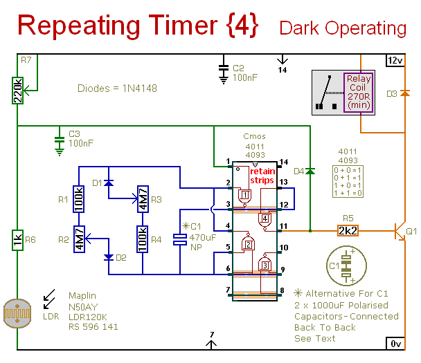
This circuit is the inverse of Repeating Timer No. 3. Its operation can be restricted to nighttime hours. The variable resistor (preset) allows selection of the darkness level at which the timer will activate. The described circuit functions as a...
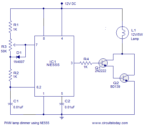
A simple PWM lamp dimmer using the NE555 timer IC. The 555 timer IC is configured as a variable duty cycle astable multivibrator to control the brightness of the lamp. The described circuit utilizes the NE555 timer IC, a versatile...

This is a programmable clock timer circuit that utilizes individual LEDs to indicate hours and minutes. Twelve LEDs are arranged in a circle to represent the 12 hours of a clock face, while an additional 12 LEDs are positioned...

This is a simple smoke alarm circuit using a timer IC, the NE555. The circuit operates by illuminating a Light Dependent Resistor (LDR) with a lamp. When smoke obscures the light from the lamp, the resistance of the LDR...
This circuit turns off an amplifier or any other device when a low-level audio signal fed to its input is absent for 15 minutes at least. Pushing P1, the device is switched on, feeding any appliance connected to SK1....
The circuit presented this month is a basic configuration of the very versatile 4017 IC Chip. In the most common use of the IC, it will turn on 10 separate outputs sequentially. Typically, the circuit is used to turn...