
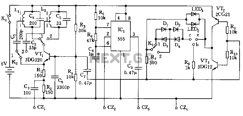
Switching Delay Used by 555 Timer IC

The circuit functions as a noise filter for a remote-controlled garage door opener by ensuring that only sustained signals can trigger the mechanism, thus preventing accidental activation from transient noise. The use of a NAND gate (IC1.C) is critical to the design, as it requires both inputs to be high for the output to activate, effectively creating a logical AND condition. The integration of a 555 timer configured as a monostable multivibrator allows for a delay mechanism, where the circuit can ignore quick, unwanted signals while responding to longer, intentional signals.
The timing characteristics of the circuit are determined by the resistor (R7) and capacitor (C5) values connected to the 555 timer. These components set the duration for which the circuit will wait before allowing the output to activate, effectively filtering out any brief noise spikes. The design also includes a transistor (T1) that acts as a switch, conducting when the circuit is triggered, and another transistor (T2) that momentarily allows the 555 timer to start its timing sequence.
The RC network at the input of IC1.D plays a crucial role in shaping the signals and ensuring that transient pulses do not affect the overall operation of the circuit. This network smooths out any short-duration signals and helps maintain stability in the output. The reset functionality of the 555 timer provides an additional layer of control, ensuring that the circuit can quickly return to its inactive state after a trigger signal is removed.
Overall, this circuit effectively addresses the issue of unwanted activations in remote control applications, enhancing the reliability and usability of devices such as garage door openers, electric shutters, and alarms.The circuit described here was designed as an addition to a remotely controlled garage door opener. The problem was that a brief burst of interference, arising from a thunderstorm or a mains spike, was enough to trigger the mechanism, and the author found this a nuisance. The effect of the circuit is to enable the output from the receiver module o nly when a relatively long pulse (more than about 0. 5 s) is received. The circuit can of course also be used in other similar situations, such as electrically-powered shutters, alarms and the like. At the heart of the circuit is NAND gate IC1. C. The output of the circuit (after inverter IC1. D) only goes high when both inputs to IC1. C are at a high level. When the circuit is triggered T1 conducts, and the output of inverter IC1. A, and hence also pin 8 of IC1. C, go high. If we now arrange things so that for a preset time the other input to IC1. C remains low, the trigger signal will not be propagated to the out-put until this period has elapsed.
In the case of the author`s garage door opener, this will only happen if the button on the transmitter is held down. The 555 timer is used to generate the delayed gating signal for IC1. C. It is wired as a monostable multivibrator in a similar fashion to the arrangement in the Economy Timer` circuit elsewhere in this issue.
When the circuit is triggered T2 will briefly conduct as a result of the positive edge at the output of IC1. A. This triggers the 555 timer: its out-put will go high, and thus pin 9 of IC1. C will go low. Because of the propagation delays through the components a very short low pulse will appear at the output of IC1.
C when the circuit is triggered. The RC combination at the input to IC1. D ensures that this does not affect the output. When the period of timer IC2, as determined by R7 and C5, expires its output returns low. This allows the input signal to pass through IC1. C. If the button on the remote control has been released before the timer expires, no signal will pass to the output. When the trigger signal is removed the out-put of IC1. A goes low, which resets the timer: the 555`s reset input, like its trigger input, is active low. The circuit is now again in its quiescent state. 🔗 External reference
Related Circuits

This is a circuit for a mosquito repellent that operates using high-frequency sound. It utilizes commonly available and low-cost electronic components. The circuit includes integrated circuits such as the IC 555 and 4017. The mosquito repellent circuit employs a high-frequency...
The overhaul includes features such as online judge diodes, the ability to test whether transistors are functioning properly, and the capability to assess TTL logic levels or high impedance states. It can output signals at 37 MHz, bar television...
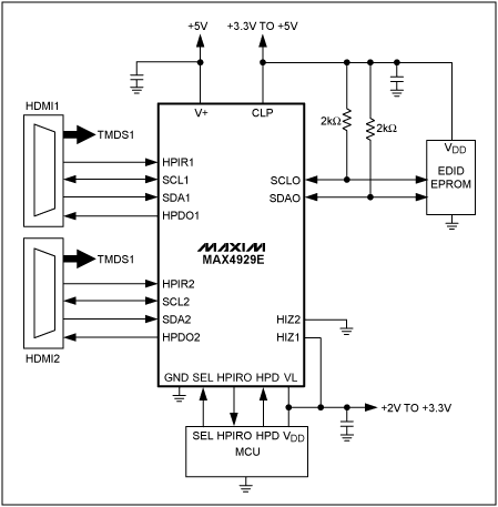
This application note outlines the functionality of the MAX4929E, which manages the switching of all low-frequency signals (LoF) required for a 2:1 HDMI/DVI switch while providing high-level ESD protection for all external lines. It also details how the MAX4929E...
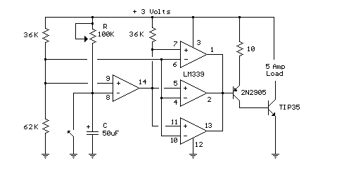
In this circuit, an LM339 quad voltage comparator is used to generate a time delay and control a high current output at low voltage. Approximately 5 amps of current can be obtained using a couple of fresh alkaline D...
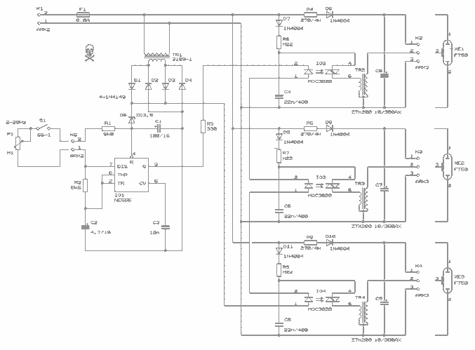
This circuit enables observation of movement between other stroboscopes. Generation of rectangular signal is based on NE555. This circuit requires a low power supply that is made from a simple transformer TR1, traditional rectifier bridge and zener diode. NE555...
This is the circuit diagram of a touch-activated alarm system that remains operational during power outages. The alarm system is triggered when someone touches the designated touch plate. A notable feature of this circuit is the automatic battery activator,...