
10 Step LED Circuit

The circuit utilizes a CD4017 decade counter, which is a versatile component designed to count pulses and drive output devices such as LEDs. The operation begins with the closure of switch S1, which triggers the counter to increment its count by one. Each output pin (Q0 to Q9) corresponds to a specific count value and is designed to activate an LED when that count is reached.
The CD4017 has ten output pins, allowing it to count from 0 to 9. When the count reaches 10 (which corresponds to the maximum count of 9 on the output pins), the counter resets automatically, returning to 0 and restarting the counting cycle. This behavior is ideal for applications requiring sequential activation of multiple outputs, such as LED indicators.
In this configuration, each LED is connected to its respective output pin of the CD4017. A current-limiting resistor is typically placed in series with each LED to prevent excessive current flow, which could damage the LEDs. The value of these resistors can be calculated based on the forward voltage drop of the LEDs and the supply voltage used in the circuit.
The reset feature of the CD4017 can be utilized if external control is needed to reset the counter manually. This is accomplished by connecting the reset pin to a switch or another control signal. However, in this basic configuration, the automatic reset functionality suffices for continuous operation.
Power supply considerations must also be taken into account, ensuring that the CD4017 is powered within its specified voltage range (typically 3V to 15V) and that the LEDs are rated for the same voltage or appropriately connected to avoid damage.
Overall, this circuit provides a straightforward method for counting pulses and controlling multiple outputs in a sequential manner, making it suitable for various applications in electronic projects.Each time switch S1 is closed the count on the CD4017 advances by 1 step and the coresponding LED turns on. When the maximium count plus 1 is reached for each circuit the cycle is restarted and repeats. 🔗 External reference
Related Circuits
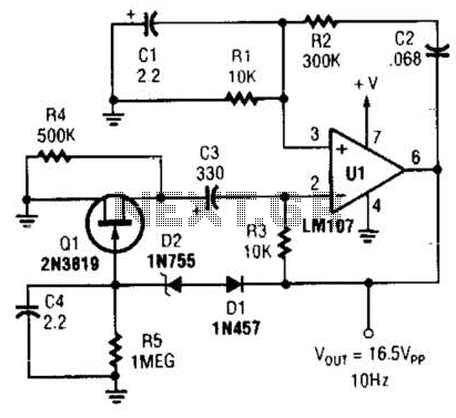
This Wien-bridge sine-wave oscillator utilizes a 2N3819 as an amplitude stabilizer. The 2N3819 functions as a variable-resistance element within the Wien bridge. The Wien-bridge oscillator is a type of electronic oscillator that generates sine waves. It employs a bridge circuit...
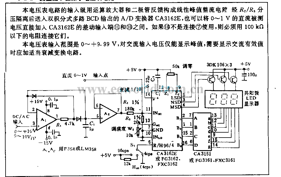
The input stage of this voltmeter circuit utilizes an operational amplifier and diode feedback to create a linear peak value rectifier circuit. A partial pressure isolation through resistors R1 and R2 directs the signal to a dual multi-channel BCD...

This circuit exhibits an exceptionally fast high-frequency response, as demonstrated by applying a 100 kHz square wave to the input. All graphs were produced using Tina Pro. The circuit's design is optimized for high-frequency applications, showcasing rapid response times that...
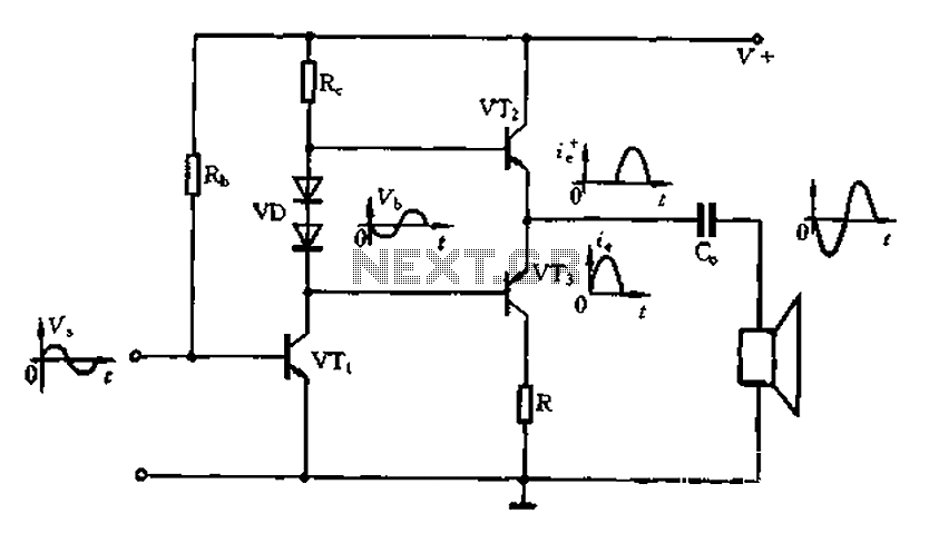
The Class A power amplifier exhibits low distortion; however, it suffers from low efficiency and limited output power, prompting the design of Class B power amplifier circuits. The Class B amplifier operates by shifting the operating point of the...

This circuit diagram represents a logic probe based on a single CMOS integrated circuit (IC). The logic probe indicates three conditions: High, Low, and Pulsing. Additionally, no LEDs will illuminate when the probe input is in a high-impedance state,...
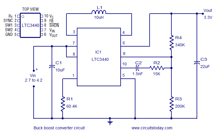
A highly efficient buck-boost converter circuit is presented, utilizing the LTC3440 buck-boost regulator IC from Linear Technology. This IC requires only one inductor and achieves efficiency levels of up to 96%. For applications where the output voltage is below...