
10 To 15W Atv Linear Amplifier

The amplifier circuit operates within the specified frequency range, ensuring efficient signal amplification suitable for various communication applications. The matching networks, comprised of capacitors and inductors, are critical for impedance matching, enhancing power transfer and minimizing signal reflections. The input matching network, formed by CI, C2, and LI, optimizes the signal received by Q1, allowing for maximum gain and efficiency.
The output matching network, consisting of L3, C3, and C4, is designed to present a 50-ohm load to the amplifier output, which is a standard impedance in RF applications. This configuration helps maintain signal integrity and maximizes the power delivered to the load.
The biasing network is essential for setting the operating point of Q1, ensuring that the amplifier functions correctly within its linear region. The inclusion of resistors R3 through R6 allows for precise adjustments to the bias current, contributing to the stability and performance of the amplifier. R1 plays a crucial role in this adjustment, enabling fine-tuning of the bias level to accommodate variations in temperature and component characteristics.
Polarity protection is provided by diodes D2 and D3, which safeguard Q1 from reverse voltage conditions that could lead to damage. The need for a heat sink is indicative of the power levels involved, as the amplifier will generate heat during operation. Proper thermal management is vital to maintain performance and reliability, preventing thermal runaway and ensuring longevity of the components.
Overall, this amplifier design incorporates essential features for robust performance in RF applications, with careful consideration given to impedance matching, biasing, and thermal protection. This amplifier is useful for applications where a 10- to 15-W peak-envelope-power (PEP) signal is needed i n the 420- to 520-MHz range. CI, C2, and LI form a matching network for amplifier Ql. L3, C3, and C4 form an output matching network for a 50- load. L2, R2, Dl, and R3 through R6 (with bias adjust Rl) form a biasing network for Ql. D2 and D3 provide polarity protection for Ql, which must be heat-sinked.
Related Circuits
.gif)
This article includes a list of references, but its sources remain unclear due to insufficient inline citations. More precise citations are needed to improve this article. Valves, also known as vacuum tubes, exhibit very high input impedance (nearly infinite...
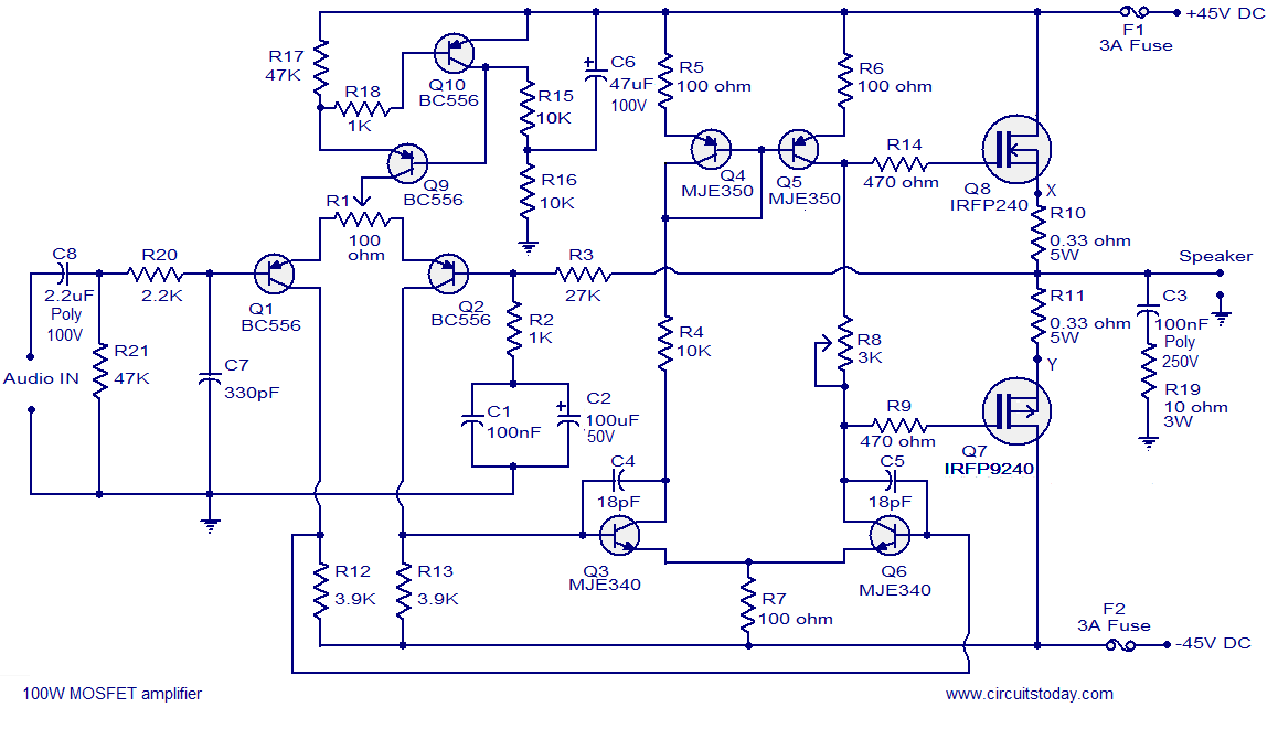
Hi-fi 100W MOSFET power amplifier circuit. Operates from a 45V dual supply. Delivers 100W to an 8-ohm speaker and 160W to a 4-ohm speaker, with low distortion. The Hi-fi 100W MOSFET power amplifier circuit is designed to provide high-quality audio...
The description refers to three circuits of the Recording Industry Association of America (RIAA), which are designed for the amplification of low signals from Moving Magnet (MM) heads. These circuits follow different solutions, each one concerning the equalization (eq). In...
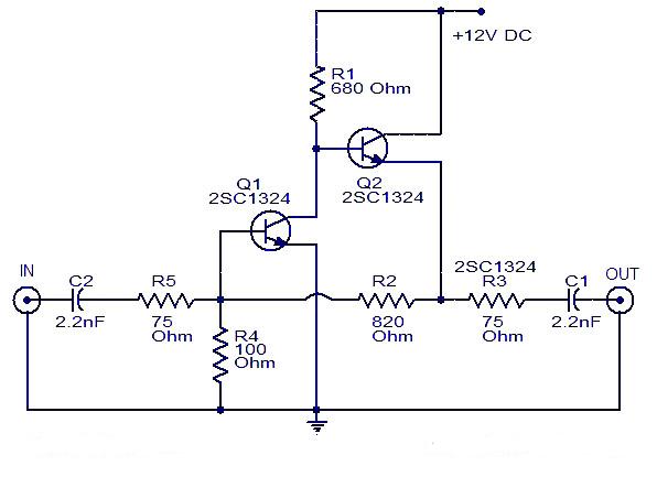
This is a cable TV amplifier utilizing two transistors. The amplifier circuit is designed for cable TV systems using 75 Ohm coaxial cables and operates effectively up to 150 MHz. Transistor T1 is responsible for amplification, providing an expected...
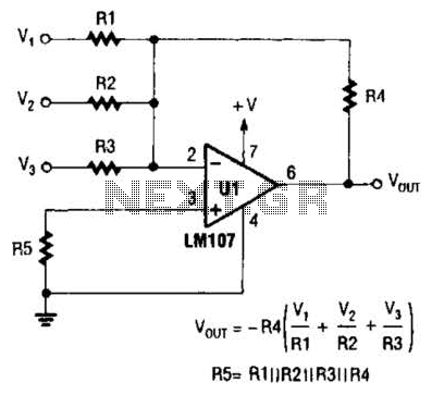
The output of Ul is the sum of Vv, multiplied by the ratio of Rx to Rv, RJRV, and respectively. Resistors R1, R2, and R3 are selected as required for individual gains. Additionally, R4 influences the gain of all...
This article discusses low dropout voltage regulator circuits (LF353DRG4). The content is straightforward and informative. The components mentioned in this article can enhance understanding of the topic. For instance, readers can find and purchase components like LF353DRG4. The article...