
10 To 1Hz Timebase Circuit

The MM5369 is a versatile timing generator IC that is commonly used in applications requiring precise frequency generation. In this circuit, the MM5369 is configured to accept a 3.579 MHz input from a parallel-mode crystal, which is known for its stability and accuracy in generating timing signals. The crystal oscillator circuit is essential for ensuring that the frequency remains stable over varying temperature and voltage conditions.
The output from the MM5369 is a 60 Hz square wave signal, which serves as a reliable clock source for further frequency division. The subsequent components, F8 and V9, function as frequency dividers. F8 reduces the 60 Hz signal to a 10 Hz signal, while V9 further divides the 10 Hz signal down to a 1 Hz output. These divisions are typically accomplished using flip-flops or counters, which take advantage of the square wave characteristics of the input signal.
The choice of the 3.579 MHz crystal (Y1) is critical, as it directly influences the precision of the derived signals. This frequency is commonly used in television applications, making the MM5369 an ideal choice for synchronization tasks in video equipment or related electronic systems. The design ensures that the output frequencies are stable and suitable for applications such as timing circuits, clock generation, and other digital signal processing tasks.
Overall, this circuit exemplifies a straightforward yet effective method for generating low-frequency signals from a high-frequency crystal oscillator, leveraging the capabilities of the MM5369 IC and the inherent stability of the selected crystal. This system uses an MM5369 IC to derive a 60-Hz signal from a TV burst crystal (3579 MHz). F8 and V9 producc a 10-Hz and 1-Hz signal from this 60-Hz signal. Y1 can be any parallel-mode 3.579-MHz crystal.
Related Circuits
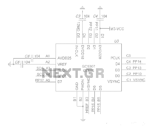
The system employs an optical fingerprint sensor utilizing the ARM Cortex M3 core, specifically the STMicroelectronics 32-bit high-performance microcontroller STM32F205RE. It incorporates a function body composition that utilizes the Sobel edge detection operator, Gabor filtering, image binarization, and various...
When the door is opened, SW1 closes, powering the circuit and turning on the lamp. C1 begins to charge slowly through R1, and when the voltage at pins #2 and #6 of IC1 reaches 2/3 of the supply voltage,...
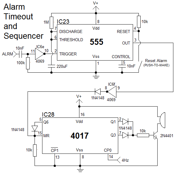
The clock is constructed using 25 CD4000 integrated circuits (ICs), three 555/556 ICs, and several discrete components. It features an alarm and a method for setting the time that is typically only seen in microcontroller designs. The complexity of...
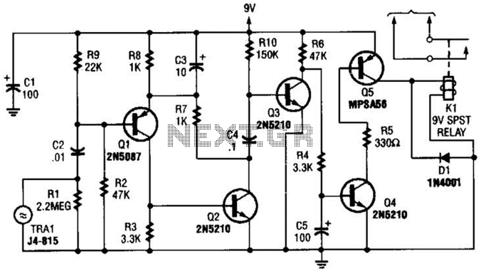
A GC Electronics P/N J4-815 transducer is utilized to receive 40-kHz acoustic remote-control signals. The receiver activates a relay to control another circuit. The GC Electronics P/N J4-815 transducer is designed specifically for the reception of 40-kHz acoustic signals, which...
Do you have disco ears? If people ask you this and you are still well below 80, you may be experiencing hearing loss, which can result from prolonged exposure to loud music. The severity of the issue may not...
The circuit operates in a parallel-fed configuration, as the DC plate current does not pass through the inductor. R3 can be substituted with an RF choke if desired. Capacitor C3 prevents B+ from appearing across the variable capacitor, which...