
Parallel fed Colpits oscillator circuit

The two halves of the variable capacitor must be identical in size or maintain a constant ratio. For narrow tuning ranges, a fixed capacitor can be placed in parallel with the variable capacitor on the grid side, while the capacitor on the plate side remains fixed. The AC voltage applied to the grid is substantial; during the positive peak, it drives the grid positive, charging capacitor C2. As the grid becomes positively charged, it attracts electrons, allowing current to flow, which causes the capacitor to charge negatively at the grid end. The grid does not become excessively positive because the capacitor retains its charge. A small amount of charge dissipates through R2 but is replenished during the next positive half-cycle. This results in a significant average DC voltage of up to -50 volts at the grid, enabling the oscillator to self-adjust. The negative bias reduces the tube's gain, allowing it to stabilize at the necessary level to maintain oscillation. When the grid voltage becomes negative, it typically drives the tube into cutoff, causing the plate current to pulse briefly. The tuned circuit resonates, producing a high-quality sine wave at the grid, although the waveform at the plate may not be as clean.
The circuit's design emphasizes stability and efficiency in oscillation. The careful selection of components such as R1, C2, and the variable capacitor ensures that the oscillator operates within desired parameters. The negative DC voltage at the grid is crucial for maintaining the oscillator's performance, allowing for automatic adjustments based on the circuit's operational conditions. The phase relationship between the voltages at the grid and plate is fundamental to the oscillator's effectiveness, ensuring that feedback is constructive and promotes sustained oscillation. Proper tuning and component matching are essential for achieving optimal performance, particularly in applications requiring precise frequency control.It is parallel fed because the DC plate current does not flow through the inductor. R3 may be replaced by an RF choke if desired. C3 keeps B+ from appearing across the variable capacitor which is generally a no no. If R1 were not present, C3 might not charge up and there would be B+ on the variable capacitor anyway. R1 makes sure that the inductor and the outer plates of the variable capacitor are held at DC ground potential.
The tuning capacitor is sometimes known as a split stator but is actually the familiar dual ganged capacitor. The rotor and drive shaft are at both AC and DC ground potential. The capacitor is, in effect, center tapped. This will place the center of the coil at AC ground potential. The effect of this is to cause the AC voltage at one end of the tuned circuit to be 180 degrees out of phase with the AC voltage at the other end.
Since the plate voltage is 180 degrees out of phase with the grid voltage, the voltage fed back to the grid has the proper phase to reinforce and sustain oscillation. The two halves of the variable capacitor need to be the same size or in a constant ratio to one another. If the oscillator is to be tuned over a narrow range, the capacitor on the plate side may be fixed and the variable capacitor on the grid side would have a fixed capacitor in parallel with it to limit its tuning range.
The AC voltage supplied to the grid is considerable. On the positive peak it drives the grid positive and C2 will be charged. When the grid is forced positive it begins to attract electrons to itself and current will flow. The grid acts like the anode of a diode. This current causes the capacitor to charge with the end of the capacitor which is toward the grid being negative. The grid never goes very far positive because the capacitor charges up and holds the charge. A small amount of charge leaks off through R2 but gets replenished on the next positive half cycle. A substantial average DC voltage, as much as -50 volts, is developed at the grid and this voltage makes the oscillator self adjusting.
The negative bias lowers the gain of the tube and it will set itself to exactly what is needed to sustain oscillation. When the grid voltage goes negative, in most oscillators this will drive the tube into cutoff. This will cause the plate current to flow in short pulses but the tuned circuit rings like a bell and the waveform at the grid is a very good sine wave.
The wave at the plate may not be as good. 🔗 External reference
Related Circuits
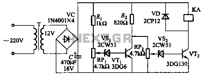
The circuit employs a transistor control mechanism. When the grid voltage is within the normal range, relay KA is activated, supplying power to the load. If the grid voltage falls below the minimum allowable threshold (adjustable via potentiometer RPz)...
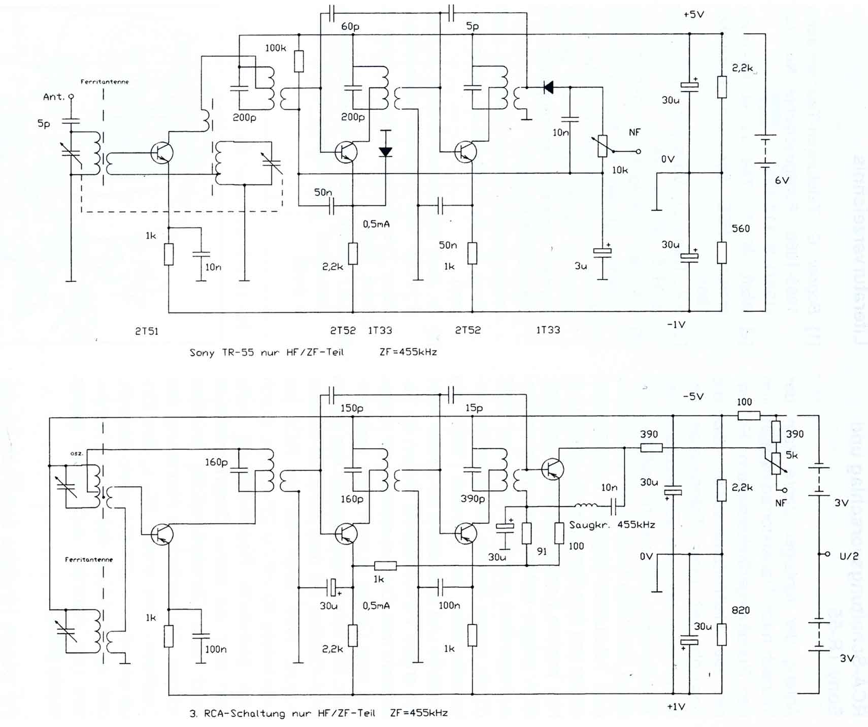
The circuitry of the Regency exhibits several unique characteristics. Notable features include the self-oscillating mixer stage, the base bias voltage of the second IF stage derived from the AF power stage, an unusual IF frequency of 262 kHz, and...
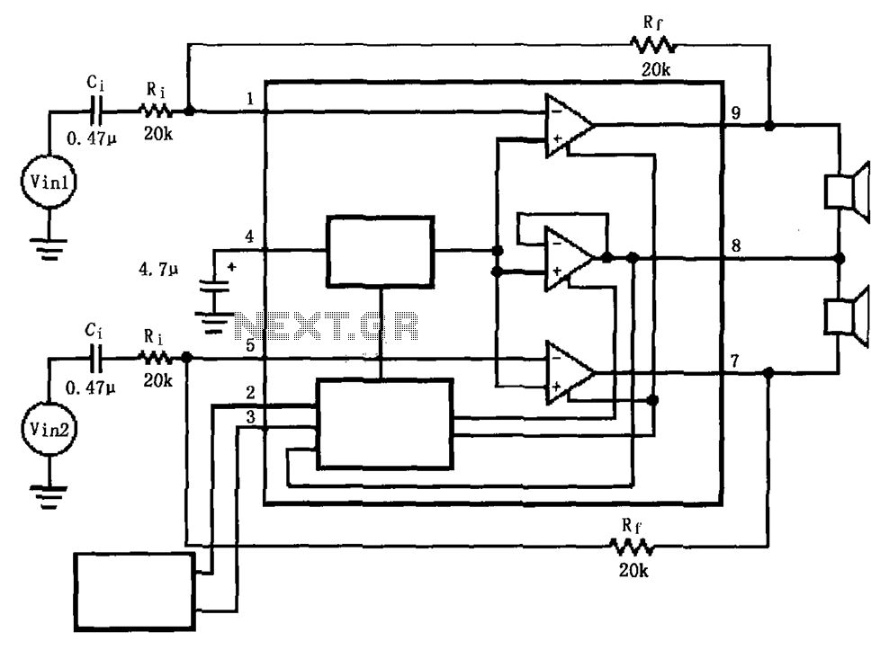
The LM4911 is presented in a configuration that does not utilize an output capacitor (OCL) for its power circuit. This design eliminates the need for squelch control (Mute), as the shutdown control (SD) responds more rapidly than the squelch...
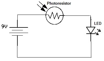
A simple photoresistor circuit will be constructed to demonstrate the operation of a photoresistor, which activates the circuit in the presence of light and deactivates it in darkness. This circuit connects a photoresistor to an LED. When the photoresistor...
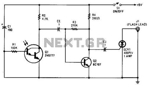
The phototransistor Q1 receives a light pulse from a photoflash unit. The pulse is AC-coupled to amplifier Q2, which subsequently triggers SCR1, activating a flash unit connected to J1. The circuit begins with the phototransistor Q1, which is sensitive to...
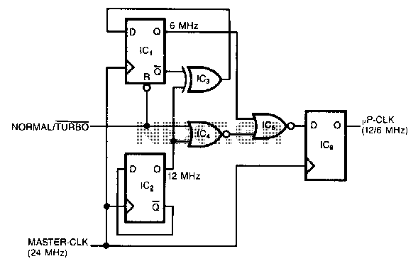
This circuit generates a dual-speed clock for personal computers. It synchronizes asynchronous switch inputs with the master clock to provide glitch-free transitions between clock speeds. The dual-speed clock allows certain programs to operate at a higher clock speed for...