
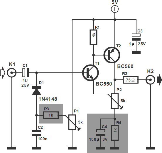
10 w amplifier using tda2003

The TDA2003 integrated circuit is a popular choice for audio amplification applications due to its robust design and reliability. It features built-in protections that enhance its durability in various operating conditions. The circuit's configuration allows for effective amplification while minimizing distortion, which is critical for high-quality audio output.
The power supply for this circuit should be capable of providing a stable voltage of 12V to 18V, with a current rating sufficient to support the load requirements. The use of capacitors C7 and C5 is essential for filtering and stabilizing the power supply, ensuring that the amplifier operates efficiently without introducing noise into the audio signal.
In the gain adjustment stage, R2 and R3 can be selected to achieve the desired amplification level. The resistor R1 plays a crucial role in setting the overall gain of the amplifier, and its value can be calculated based on the desired output power and input signal level. The design also incorporates C3, which serves as a high-pass filter, effectively blocking low-frequency signals that may not be needed in certain applications.
For high-frequency stability, C6 and R4 are strategically placed to dampen any oscillations that may occur during operation, ensuring that the amplifier remains stable even under varying load conditions. This feature is particularly important in car audio systems where environmental factors can influence performance.
Overall, this circuit design is versatile and can be tailored to suit different audio applications, making it an excellent choice for both amateur and professional audio enthusiasts.This is a circuit diagram of amplifier circuit, these circuits have a 10W audio power amplifier using TDA2003 IC from SGS Thomson popular. The IC can easily provide 10W into 4 Ohms load at 18V DC supply voltage. IC can also be operated from 12V and that makes it applicable in a car audio system. Useful features include TDA2003 short circuit protec tion between all pins, thermal overload protection, low harmonic distortion, low distortion. The circuit given here is designed according to the datasheet from the manufacturer and found to be working well. The following is a schematic drawing: C7 capacitor DC input work decoupling. R2 and R3 are used to adjust the gain of R1 determines amplifier. C3 and cut off the top frequency. C6 and R4, and is intended to increase the stability of high frequency. The capacitor C5 couples the output to the speakers. You can try this circuit diagram for your car audio power amplifier or to a small room. 🔗 External reference
Related Circuits
The video amplifier depicted in the diagram is a widely recognized design that is both simple and highly effective. However, the transistors are susceptible to damage if the potentiometers (black level and signal amplitude) are set to their extreme...
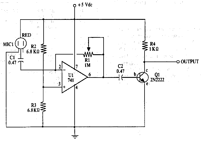
The amplifier features an adjustable gain, facilitated by R1, a 1 Mega Ohm variable resistor. This resistor regulates the feedback of the 741 operational amplifier (op-amp), which subsequently drives a 2N2222 output transistor. The circuit receives an audio signal...
This document provides a guide on understanding a simple computer system and its operation. It will examine the BASIC programming language and its statements, enabling communication with external circuitry. The document will also explore how to interface electronic circuits...
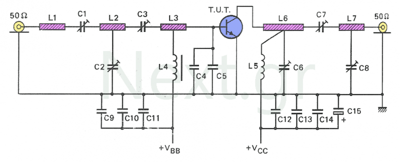
This circuit serves as an amplifier for small transmitters operating within the UHF band, specifically in the 450-800 MHz range. The amplifier operates in Class A, utilizing the well-known Philips BLW33 transistor. Although the construction is relatively simple, it...
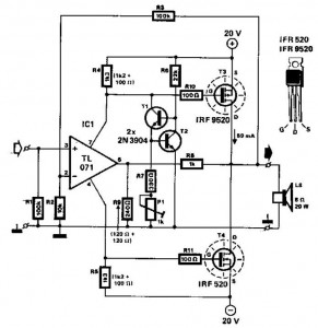
This audio power amplifier employs two complementary MOSFETs (IRF9520 and IRF520) to provide up to 20W output into an 8-ohm speaker. A TL071 operational amplifier functions as the input amplifier. The MOSFETs require heatsinking with a thermal resistance of...
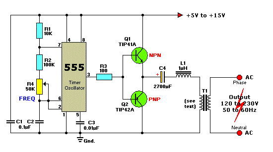
This circuit is a simple 12V DC to 220V AC inverter that produces an AC output at line frequency, specifically 220V AC, or other voltages by selecting transformer T1. The 555 integrated circuit (IC) is configured as a low-frequency...