
10w audio amplifier with bass

In electronic circuits, grounding serves as a reference point for all voltage levels within the system and is critical for maintaining signal integrity. Ground loops can introduce unwanted noise, often manifesting as hum in audio applications. To mitigate these issues, it is recommended that all ground connections be consolidated to a single point.
In this particular schematic, the components J1 (likely a connector), P1 (possibly a power input), and capacitors C2, C3, and C4 must share a common ground connection. This ensures that any potential differences between the ground points of these components are eliminated, reducing the likelihood of interference.
Furthermore, C9 should be connected to the output ground. This capacitor may be used for filtering purposes, smoothing out voltage fluctuations at the output, thus enhancing the overall performance of the circuit. By ensuring that C9 is grounded properly, it can effectively minimize noise and stabilize the output signal.
Overall, careful consideration of grounding practices is vital in circuit design to ensure optimal functionality and reliability.A correct grounding is very important to eliminate hum and ground loops. Connect to the same point the ground sides of J1, P1, C2, C3 &C4. Connect C9 to the output ground. 🔗 External reference
Related Circuits
The circuit above is a canonical AC coupled common emitter amplifier, which is typically used as a linear amplifier rather than a switch that activates when the input exceeds a certain level. The AC coupled common emitter amplifier is...
A magnetic pickup from an old record player can function effectively as a pressure and vibration sensor. By replacing the needle with a thin metal plate (copper from a PCB is suitable), an excellent touch sensor can be created....
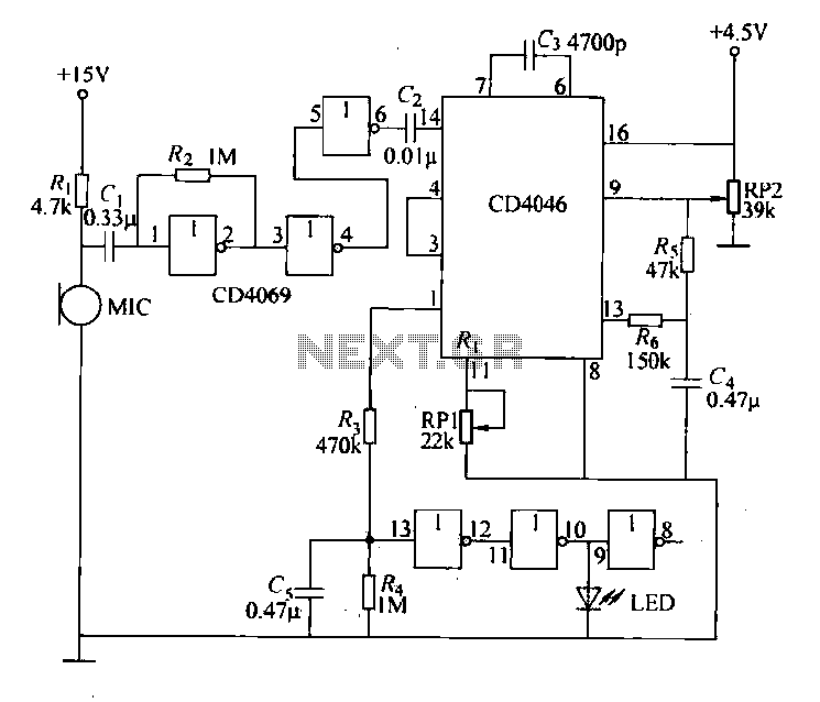
Each issue produces a specific frequency of sound, and the audio remote control will switch states based on these frequencies. The circuit is designed to detect other frequencies emitted by environmental sounds with strong anti-interference capabilities. The circuit operates...
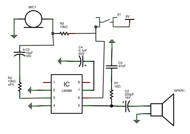
A button is utilized as a push-to-talk switch. While it generally functions correctly, there is a significant delay of approximately five seconds before any audio output is heard upon pressing the button. The described circuit involves a push-to-talk switch, which...
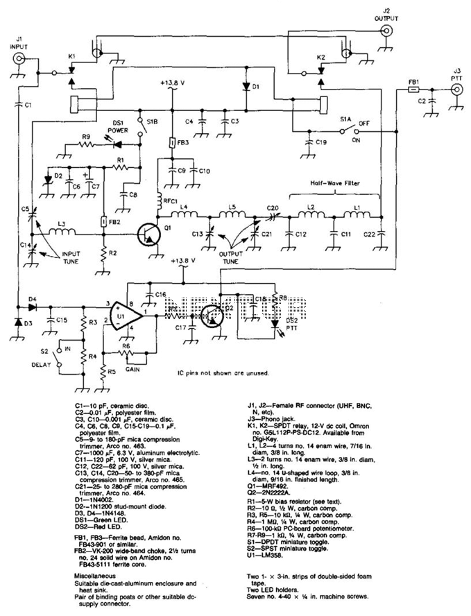
A 100 W output at 50 MHz is available from this circuit. U1 and Q2 form a T-R relay driver, switching the amplifier on when RF input at J1 is sensed. During receive periods, J1 and J2 are directly...
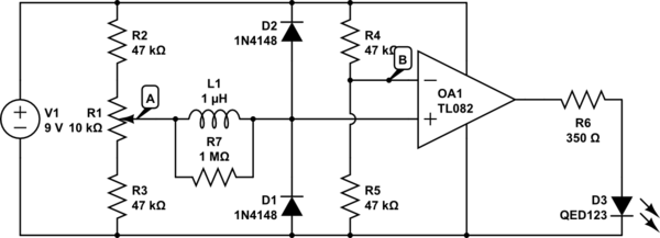
Detects clipping in preamp stages, mixers, amplifiers, etc. Single LED display powered by a 9V battery. This circuit is intended for use as a standalone unit. The clipping detection circuit is designed to monitor audio signals in various electronic devices...