
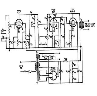
2 watt amplifier schematic diagram

The circuit employs vintage transistors, which are known for their unique characteristics that can introduce desirable harmonic distortion, often sought after in audio applications for a warmer sound. The use of older components also simplifies the design and assembly process, as these parts are typically more readily available and cost-effective.
The power supply is a standard 12V wall transformer, which provides a convenient and reliable source of energy for the circuit. This voltage level is suitable for most audio amplifier configurations, ensuring that the transistors operate within their optimal range.
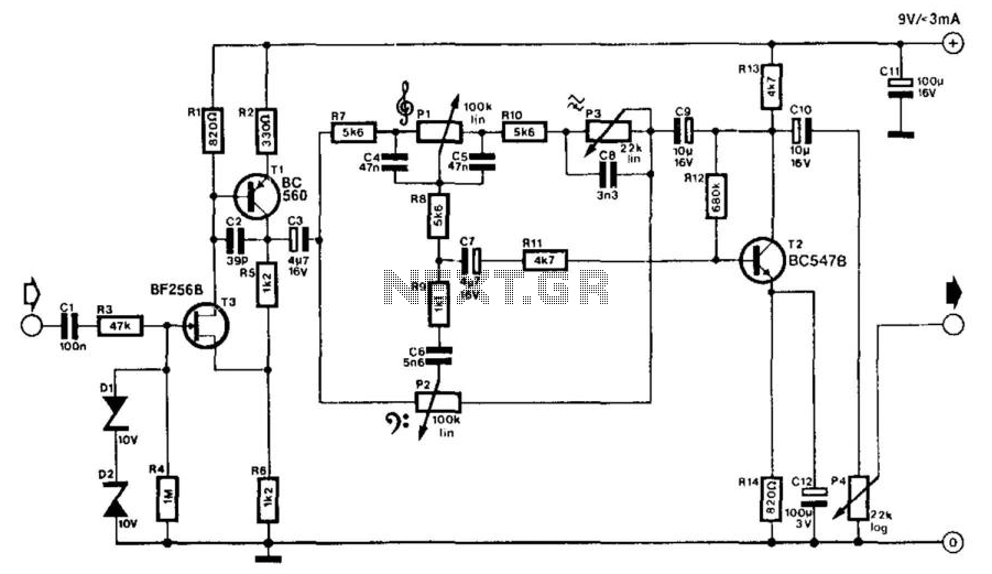
The inclusion of a bass boost feature, activated by the closure of switch SW1, enhances low-frequency response. This feature is particularly useful in audio applications where bass frequencies are crucial for overall sound quality. However, activating this feature can lead to a reduction in power at higher frequencies, necessitating an increase in the volume control to maintain a balanced audio output. This adjustment is critical to ensure that the overall sound remains clear and undistorted across the frequency spectrum.
Overall, the circuit design emphasizes simplicity and functionality, making it an effective solution for audio amplification while accommodating the nuances of sound quality through the use of harmonic distortion and bass enhancement techniques.The circuit is intentionally designed using old type transistor, it is to get the harmonic distortion and to avoid the difficulty of finding good components. Amplifier (s) can be easily supplied by plug-in wall transformer 12V. Closing SW1 bass boost is provided but, at the same time, volume control must be increased to compensate for the loss of
power at higher frequencies. 🔗 External reference
Related Circuits
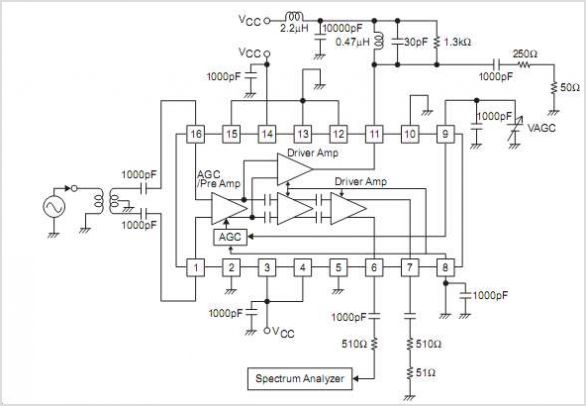
The LC72146 is a Phase-Locked Loop (PLL) Frequency Synthesizer LSI circuit designed for electronic tuning in car stereo systems. This component facilitates the development of high-performance, multifunctional electronic tuning systems across VHF, MW, and LW bands. It is manufactured...
In this circuit, a 74HC14 hex Schmitt trigger inverter is used as a square wave oscillator to drive a small signal transistor in a class C amplifier configuration. The oscillator frequency can be either fixed by a crystal or...

This project involved the design of an audio amplifier that delivers substantial output power while maintaining a minimal parts count and high quality. The power amplifier section utilizes only three transistors along with a few resistors and capacitors arranged...
The signal from a microphone is too weak for a standard line input. This low-noise DC-coupled microphone amplifier provides a solution for anyone who wants to connect a microphone to a high-fidelity installation. As shown in the schematic diagram,...
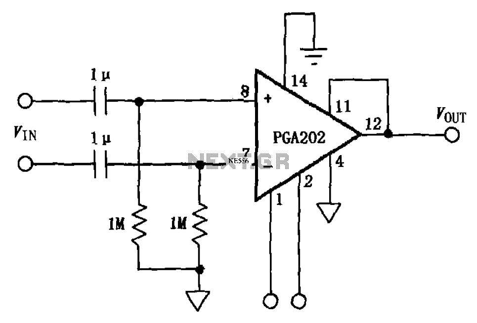
The circuit illustrated in FIG PGA202 comprises an AC-coupled differential amplifier. The input stage of PGA202 includes two 1 µF capacitors and two 1 MΩ resistors, resulting in a cutoff frequency of approximately 0.16 Hz. The Qualcomm AC coupling...
An electric guitar often needs to be connected to a mixing panel, a tape deck, or a portable studio. While cabling is typically not an issue, the challenge lies in matching the high impedance of the guitar pickup to...