
1000 watt power inverter schematic

The 1000-watt power inverter circuit is designed to convert DC voltage into AC voltage, making it suitable for powering various electronic devices. The core component, the RF50N06 MOSFET, features a robust rating of 60 volts and 50 amps, allowing it to handle substantial power levels efficiently. When higher output is required, additional RF50N06 MOSFETs can be paralleled to increase the overall current capacity, ensuring that the inverter can meet the demands of more power-intensive loads.
In the schematic, the MOSFETs are typically arranged in a half-bridge or full-bridge configuration, which is essential for generating the desired AC waveform. The gate drive circuitry must be carefully designed to switch the MOSFETs on and off at the appropriate frequency, commonly in the range of several kilohertz, to produce a stable output waveform. A pulse-width modulation (PWM) technique may be employed to control the output voltage and frequency, providing versatility for different applications.
Incorporating a fuse in the power line is a critical safety measure. It protects the circuit from overcurrent situations that could lead to component failure or fire hazards. The fuse should be rated appropriately for the maximum expected current to ensure reliable operation while safeguarding the circuit.
The output transformer plays a vital role in this inverter circuit. It steps up the voltage to the desired level for AC applications. The choice of transformer affects the efficiency and performance of the inverter, and experimenting with different transformer designs can yield improved results. Users are encouraged to explore custom transformer configurations to optimize power output and efficiency based on their specific needs.
Overall, this power inverter circuit is a versatile solution for converting DC power into AC power, suitable for a wide range of applications, from small electronic devices to larger appliances, depending on the transformer and load configuration used.This 1000 watt power inverter circuit diagram based on MOSFET RF50N06. If you want more power then add additional MOSFET paralleled at RF50N06. This MOSFETS are 60 Volts and 50 Amps as rated. It is necessary to connect a FUSE with the power line and always a LOAD have to connected while power is being applied. The output power of this inverter is u p-to 1k watt, it depends on output power transformer. You can use your custom transformer with experimenting for best result. 🔗 External reference
Related Circuits
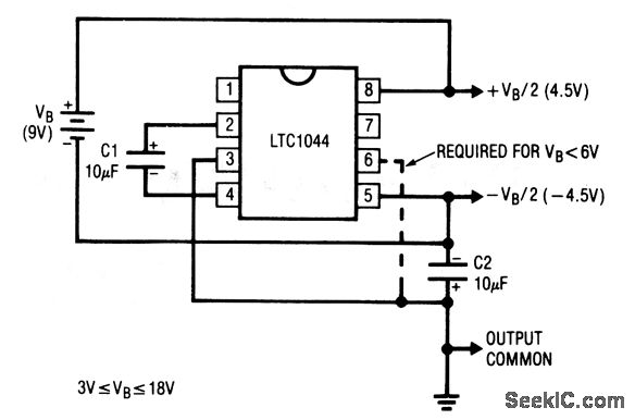
This circuit generates symmetrical ±output voltages, each equal to one-half of the input voltage (for example, a single 9-V battery). The output voltages are referenced to pin 3, which serves as the output common. The circuit is compatible with...
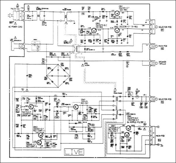
A 12V switching power supply schematic has been observed to generate significant heat, which has prompted discussions among users in prominent forums, such as dp. The 12V switching power supply is a crucial component in various electronic applications, providing...
The 2N388A transistors are inexpensive (approximately 18 cents when purchased in lots of five or more). The 2N5088 transistors are readily available from Mouser. Other components can typically be sourced from Radio Shack or local stores. To convert to...
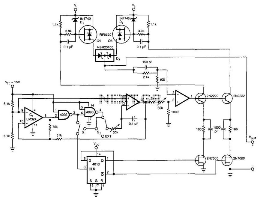
This power booster operates as a high-efficiency power multiplexer or, when supplied with an external signal source, as a high-power linear amplifier. For driving a load with a high-power square wave, the circuit alternately draws power from two external...
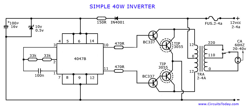
An article on how to create an inverter using a simple 40-watt inverter circuit diagram and schematics. This inverter converts 12 volts to 220 volts using the CD4047 integrated circuit. The described inverter circuit utilizes the CD4047 IC, which is...
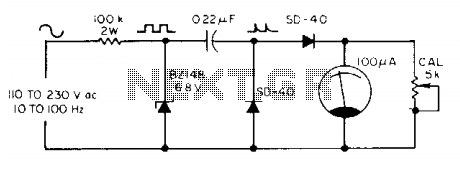
The meter utilizes a zener diode to convert input sine waves into square waves. After calibration with a 5 k ohm potentiometer, the 100 µ meter provides a direct reading in hertz. The circuit employs a zener diode as a...