
How to make an Inverter-Simple 40 Watts Inverter Circuit

The described inverter circuit utilizes the CD4047 IC, which is a versatile component capable of functioning as either an astable multivibrator or a monostable multivibrator. In this application, the IC operates in astable mode to generate a square wave output that is essential for driving the inverter's power stage.
The circuit typically consists of several key components: the CD4047 IC, a transformer, capacitors, resistors, and a power transistor or MOSFET. The 12-volt input is fed into the CD4047, which produces a square wave output at a frequency determined by the external resistor-capacitor (RC) network connected to its timing pins. This output is then fed into the primary winding of a transformer, which steps up the voltage to the desired 220 volts AC.
To ensure proper operation, the circuit should include filtering capacitors to smooth out any voltage spikes and protect the components from high-frequency noise. Additionally, the transformer must be rated appropriately for the expected load, with a sufficient turns ratio to achieve the necessary voltage conversion.
The power stage may involve a push-pull configuration using transistors or MOSFETs to efficiently switch the current through the transformer, ensuring that the inverter can deliver up to 40 watts of power. Proper heat dissipation measures, such as heat sinks, should be employed to prevent overheating of the power devices.
Overall, this inverter design provides a practical solution for converting low-voltage DC power to high-voltage AC power, suitable for a variety of applications, including powering small appliances and electronic devices.An article on How to make an inverter using simple 40 Watts inverter circuit diagram and schematics. This is a 12 volts to 220 Volts inverter using CD4047 IC.. 🔗 External reference
Related Circuits
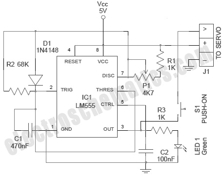
A servo is an error-sensing feedback control mechanism used to correct the performance of a system. A servo motor is a DC motor equipped with a servo mechanism. A servo motor is an electromechanical device that utilizes a closed-loop control...
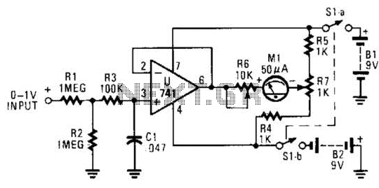
The circuit is designed around a 741 general-purpose operational amplifier (op amp) configured as a voltage follower, providing a voltage gain of one. The output from the 741 is utilized to drive a 50-meter movement. Potentiometer R7 is employed...
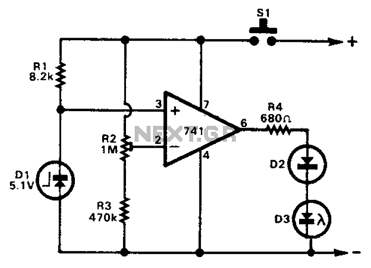
The 741 operational amplifier can function as a voltage comparator. It features a non-inverting input and a Zener-controlled voltage source, with a reference voltage set at 5.1V. Resistor R2 is used to adjust the in-phase input voltage to half...
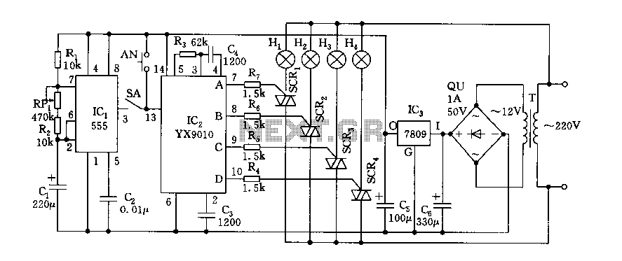
Fantasy lights offer wonderful changes suitable for storage, dance halls, or family holiday decorations. The control circuit is depicted here, which includes a multivibrator control circuit, a thyristor trigger circuit, and a step-down power supply circuit. The AC step-down...

The multi-purpose signal generator circuit consists of integrated circuit oscillators and frequency dividers. It generates square waves ranging from high frequencies to sub-audio frequencies and also produces a frequency standard in the VHF range. The alternative oscillator section feeds...
This circuit is designed for applications where over-current protection is necessary. An example can be found in the model train hobby. Experienced model train enthusiasts understand that troubleshooting a short-circuit can be quite challenging. While it is relatively easy...