
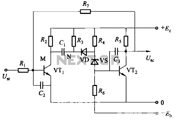
100v / 10ma regulator circuit

The circuit is designed to ensure reliable operation under varying load conditions, incorporating both no-load and short circuit protection functionalities. The use of resistors R1 and R2 plays a critical role in managing power dissipation during fault conditions. Resistor R1, with a resistance of 1.2kΩ and a power rating of 20W, is positioned to limit current flow during a short circuit while allowing adequate heat dissipation. Similarly, resistor R2, rated at 220Ω and 4W, serves to further stabilize the circuit under fault conditions.
The output voltage (U2) is maintained at 100V, with the circuit capable of delivering an output current (I2) of up to 10mA. The input voltage (U1) is designed to operate within the range of 120V to 180V, providing flexibility for different supply conditions. The specified thermal resistance of the radiator (Rthk = 20°C/W) indicates that the design should effectively manage heat generated during operation, ensuring that the components remain within safe temperature limits.
Output voltage variations are carefully controlled; when the input voltage (U1) is within the specified range and the circuit is under rated load, the output voltage (U2) is approximately 1V. In contrast, under no-load conditions, the output voltage increases to 1.5V. This behavior is crucial for maintaining circuit stability and ensuring that the output current (I2) can be effectively regulated from 0 to 10mA, depending on the load conditions.
The ambient temperature range of 0°C to 60°C indicates that the circuit is suitable for a variety of operational environments. The output voltage's sensitivity to temperature, quantified as a variation of 150mV per degree Celsius, emphasizes the importance of thermal management in the overall circuit design. Proper heat dissipation strategies must be implemented to maintain performance and reliability across the specified temperature range.There are no-load and short circuit protection short circuit protection. To allow time short circuit, it must increase the resistors R1 and R2 allows power dissipation, such as R1 = 1.2k Europe, 20W; R2 = 220 Europe, 4W. Technical data: Output voltage: U2 = 100V; Output Current: I2 = 10mA; Input voltage: U1 = 120 ~ 180V; radiator thermal resistance: Rthk = 20grd / W; Output voltage variation: input voltage U1 = 120 ~ 180V when the rated load and U2 = 1V; U1 = 120 ~ 180V and no-load U2 = 1.5V; output current I2 = 0 ~ 10mA (U1 = constant) when U2 = 1.5V; ambient temperature 0u = 0 ~ 60 when Celsius U2 = 150mV / grd.
Related Circuits
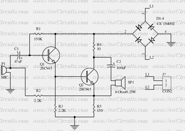
This is the basis of electronics telephone sets. You can use it to replace the talking circuit of an old telephone set with new design, better noise rejection and reliability one. Also you can use it to build a...
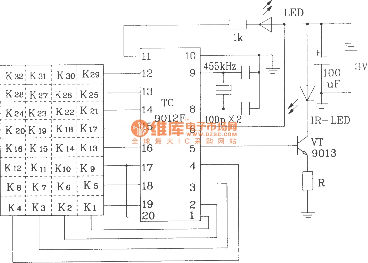
The TC9012 is a specialized off-screen remote control code transmitter. It incorporates an oscillator, divider timing generator, system code latch, data storage, key scan input, key scan output, and carrier control and output units. The internal 8-bit system code...
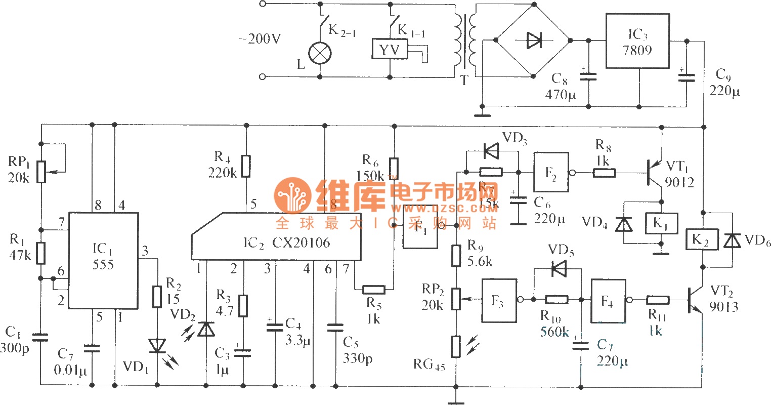
The circuit consists of the following components: (1) An infrared emitter which utilizes a multi-harmonic oscillator based on a 555 timer circuit. The oscillation frequency is determined by the values of RP1, R1, and C1, resulting in a frequency...
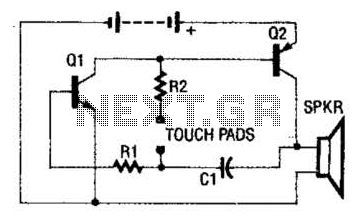
The circuit employs a two-transistor direct-coupled oscillator, with its frequency determined by capacitor C1, resistor R2, and the skin resistance across the touch pads. Since C1 and R2 are fixed values, only the skin resistance can vary the sound...
Rechargeable ago memory circuit. Before the memory circuit is activated, a delay reset circuit is utilized. When the input signal triggers an action, timing begins, and after a specified delay, the circuit reverts to its original state. During this...
All electronic circuits were initially built on breadboards. Once the circuits were operational, they were soldered onto perfboards to create a more durable system. A power board was designed to stack two batteries in series, providing access to a...