
Rechargeable ago memory circuit
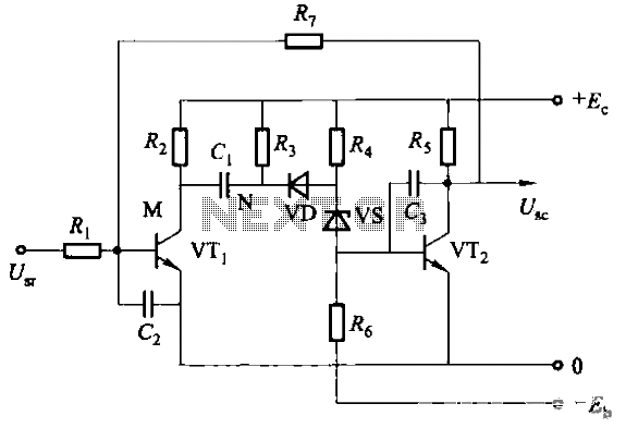
The rechargeable ago memory circuit incorporates a delay reset function that enhances its operational reliability. The circuit is designed to respond to an input signal, initiating a timing sequence. This sequence is crucial as it determines the duration for which the circuit remains active. Once the input signal is detected, the timing mechanism starts, and the circuit enters an operational state, producing an output signal.
The delay reset circuit is integral to the functionality of the memory circuit. It ensures that the system remains in the active state for a predetermined duration, even in the presence of continuous input signals. This is particularly useful in applications where transient signals may occur, as it prevents the circuit from immediately resetting and allows for a stable output during the timing period.
The single-shot configuration of this circuit means that it will only trigger once per input signal, regardless of how long the signal persists. After the delay period expires, the circuit will automatically reset to its initial state, ready to respond to any subsequent input signals. This characteristic is essential for applications where precise timing and control are necessary, such as in pulse generation, timers, and event counters.
Overall, the rechargeable ago memory circuit with its delay reset feature provides a robust solution for managing input signals and ensuring consistent output behavior, making it suitable for various electronic applications.Rechargeable ago memory circuit Before the memory circuit is considered instantaneous action, the delay reset circuit. When the input signal to one that is action, and start timing, after after a delay, the circuit returns to the original state. During this period, regardless of whether the input signal is persistent, the circuit remains operation state, and the output signal.
It is actually a single-shot.
Related Circuits
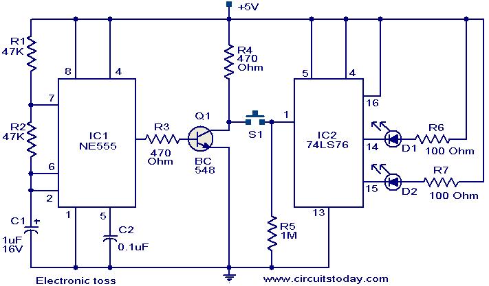
The circuit described can be utilized for tossing a coin, serving as a random generator for head or tail outcomes. This circuit is applicable in various games where a coin toss is required to initiate play. It employs two...
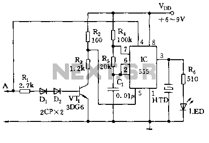
The circuit utilizes a 555 timer along with resistors R4, R5, and capacitor C1 configured in a controllable multivibrator mode. This setup forces the reset terminal (pin 4) to a specific state, allowing for control of the external logic...
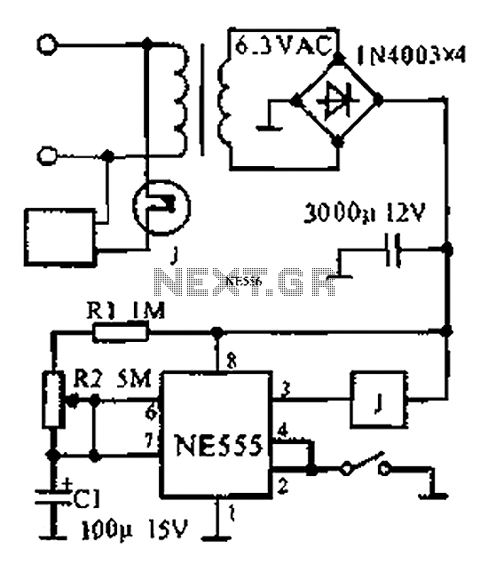
The provided information indicates that when the power supply operates between 0 to 1 hour, an AC circuit diagram is established using a 555 timer configured as a one-hour timer. The relay utilized is a J 212 IRC MR312C...
One cannot expect high performance from a basic detector-based meter. Its sensitivity is merely sufficient to provide a fundamental understanding of the power output that the transmitter can achieve. The detector-based meter operates on a straightforward principle where it measures...
The following circuit illustrates the connection of the Devantech SRF04 Ultrasonic Sensor to the SV203 powered PPRK Circuit Diagram. This circuit is based on the Devantech SRF04 sensor and features a minimum initiation time of 10 milliseconds for the...
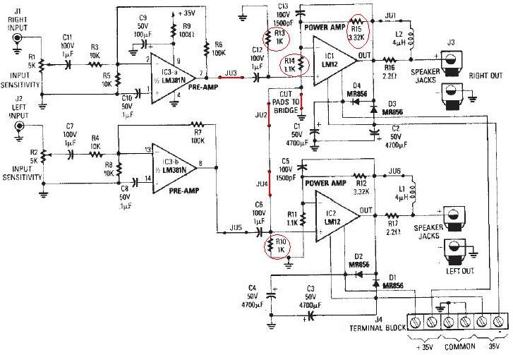
The LM12 audio amplifier circuit is designed to deliver high output power for loads with impedances of 4 ohms or 8 ohms. The maximum output power achievable by this amplifier is approximately 60 watts for a 4-ohm load and...