
100W Audio Amplifier
The described circuit is a high-fidelity audio amplifier that operates from a symmetrical -40 VDC power supply, capable of delivering a maximum output current of 2.6 A. The design incorporates a differential amplifier configuration utilizing transistors Q4 and Q5, which are crucial for maintaining signal integrity and ensuring that no DC offset is present at the output. This is particularly important as DC voltage across the speaker can lead to damage. The inclusion of DC feedback in this configuration stabilizes the circuit and enhances linearity.
Transistor Q11 functions as a constant current source, providing a steady biasing current of 1 mA to the input stage. This consistent current flow is essential for maintaining the performance of the differential amplifier, ensuring that it operates efficiently across varying signal conditions. The voltage drop generated across the resistor connected to the collector of Q4 is an important signal that is utilized to drive the subsequent driver stage.
The driver stage is composed of a Darlington pair formed by transistors Q3 and Q2. This configuration is advantageous for its high current gain, allowing the amplifier to drive larger loads with minimal input signal. The current source Q10, which provides a constant current of 7 mA to the driver stage, ensures that the Darlington pair operates effectively, maintaining the desired output characteristics while minimizing distortion.
Overall, this circuit design emphasizes stability, efficiency, and protection of the speaker, making it suitable for high-performance audio applications. The careful selection of components and their configuration ensures that the amplifier can deliver high-quality sound reproduction while safeguarding the connected audio equipment.The circuit works from a symmetrical 40 VDC power supply and draws a maximum current of 2.6 A. The input circuit of the amplifier is a differential amplifier built around Q4 and Q5 that employ DC feedback thus preventing any DC voltage from appearing across the speaker with the usual destructive results. Q11 acts as a current source and ensures that the input stage draws a constant current of 1 mA. The signal which appears as a voltage drop across the resistor connected in series with the collector of Q4 is used to drive the DARLINGTON pair Q3, Q2 which together with the constant current source of 7 mA that is Q10, form the driver stage. This stage 🔗 External reference
Related Circuits
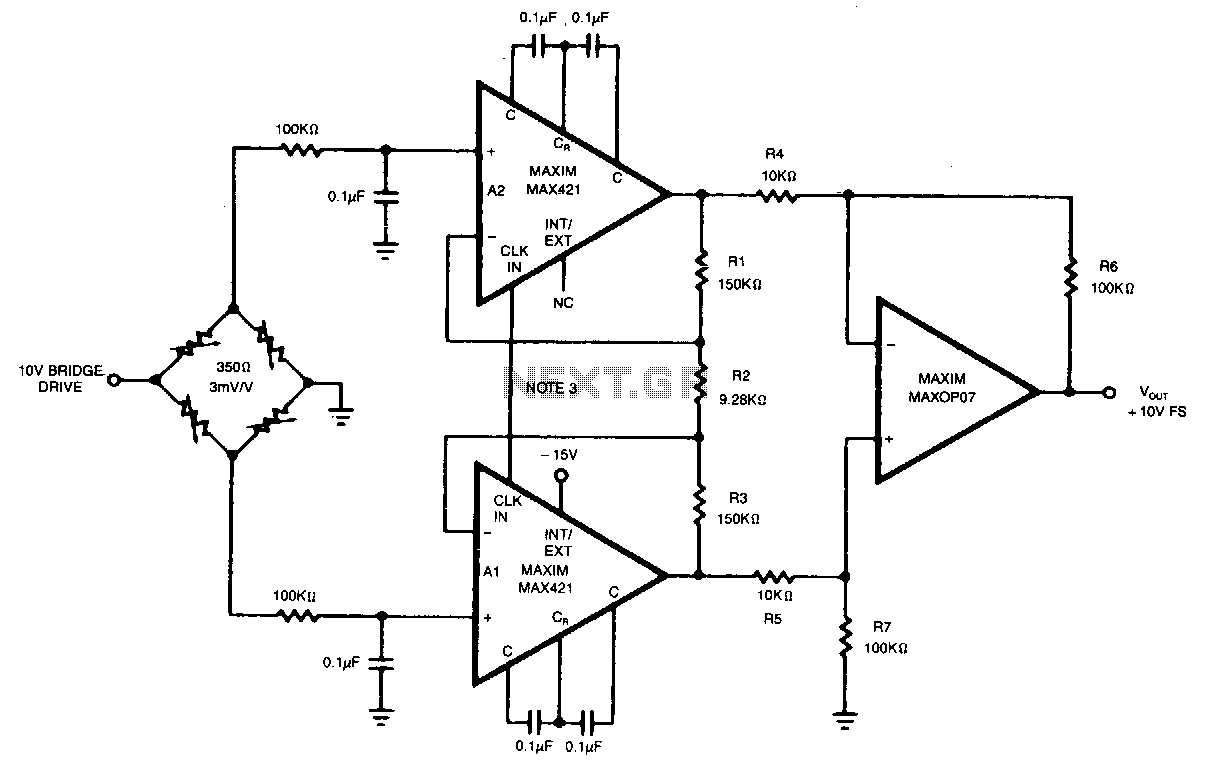
This circuit achieves an overall gain of 320. Additional gain can be obtained by decreasing the value of R2. The untrimmed Vas is 10.11V, and the Vas temperature coefficient is less than 0.1µV/°C. In various applications, the OP07 can...
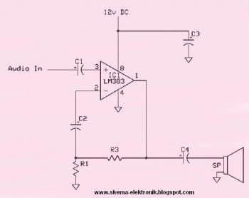
This circuit is an 8W audio amplifier utilizing the LM383 integrated circuit as its primary component. It is designed to be simple, cost-effective, and easy to assemble. Component part list: - C1: 10μF Electrolytic Capacitor - C2: 470μF Electrolytic Capacitor - C3:...
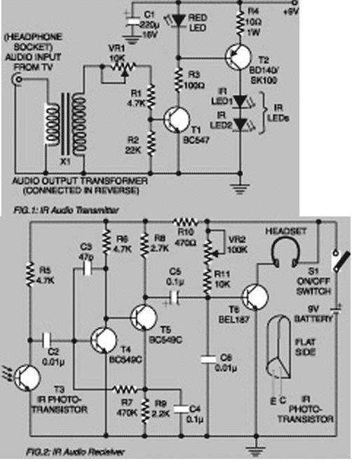
Using this low-cost project one can reproduce audio from TV without disturbing others. It does not use any wire connection between TV and headphones. In place of a pair of wires, it uses invisible infrared light to transmit audio...
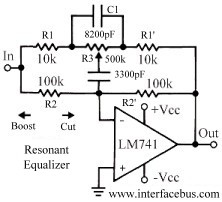
This topic discusses a resonant equalizer, which is a distinct type of circuit compared to the standard audio equalizer, although both achieve similar outcomes. The key difference is that the frequency responses of both the high and low frequency...
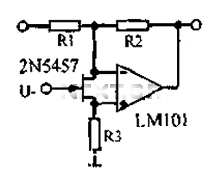
A 1.53 voltage-controlled gain amplifier (VGA) utilizes a FET connected between the two inputs of the operational amplifier (op-amp) as a voltage-controlled resistance. The resistance changes linearly with voltage and varies from several dozen square ohms, exhibiting excellent control...
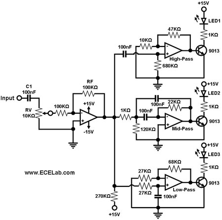
Figure 1 illustrates a simple circuit designed for converting an audio signal (such as one from the output terminals of a CD player). The circuit primarily consists of a buffer/amplifier stage and three filtering circuits: a high-pass filter, a...