
10M Dsb Qrp Transmitter With Vfo Circuit

The 10-meter SSB transmitter schematic consists of three fundamental components, each designed to facilitate specific functions within the transmission process. The first component, the Variable Frequency Oscillator (VFO) board, employs a Field Effect Transistor (FET) as a transmission oscillator. This configuration allows for stable frequency generation, which is crucial for SSB (Single Sideband) transmission. The VFO signal is mixed using an NE602 mixer, a popular choice for its low power consumption and good performance in RF applications. The output from the mixer is then amplified by transistor Q2, ensuring that the signal reaches a sufficient power level of +7 to +10 dBm, which is necessary for driving the subsequent SBL-1 mixer in the transmit mixer stage.
The second component, the balanced mixer/modulator board, utilizes an 11-MHz crystal oscillator. This oscillator provides a precise frequency reference, which is essential for maintaining the integrity of the modulated signal. The diode-balanced mixer effectively combines the incoming audio modulation with the RF signal, allowing for the creation of a Double Sideband (DSB) signal. This DSB signal is then routed to a 28-MHz band-pass filter, which serves to eliminate unwanted frequency components and ensure that only the desired signal is transmitted.
The final component is the 1-W amplifier board, which is designed to amplify the processed signal for transmission. This board features a three-stage amplifier configuration, which enhances the signal strength while maintaining linearity to prevent distortion. Additionally, the board includes transmit/receive switching circuitry, allowing for seamless transitions between transmitting and receiving modes. This comprehensive design ensures that the 10-meter SSB transmitter operates efficiently and effectively, with each block contributing to the overall functionality of the system. The three schematics represent three building blocks for a 10-meter SSB transmitter. Or these blocks can be used separately as circuit modules for other transmitters. The VFO board uses an FET transmittal oscillator, the VFO signal is mixed in an NE602 mixer and is amplified by Q2 to a level sufficient to drive an SBL-1 mixer in the transmit mixer stage (+7 to +10 dBm). In the balance mixer/modulator board, an 11-MHz crystal oscillator drives a diode balanced mixer. Audio for modulation purposes is also fed to this mixer. The DSB signal feeds a 28-MHz BPF. The 1-W amplifier board consists of a 3-stage amplifier and transmit/receive switching circuitry.
Related Circuits
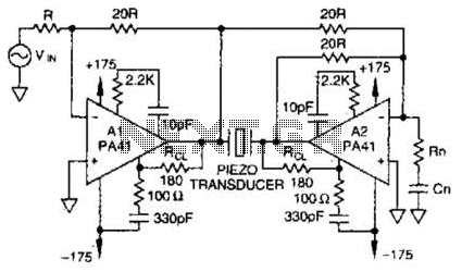
Using a PA41 from Apex Microtechnology, this monolithic amplifier is capable of 350-V operation and delivers 660 V peak-to-peak in a bridge circuit. The PA41 is a high-performance monolithic amplifier designed for applications requiring high voltage and high power output....
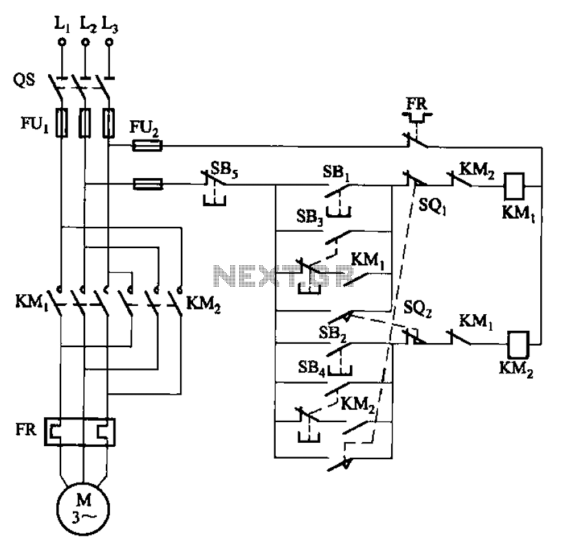
The circuit depicted in Figure 3-27 features a jog function that allows for precise adjustments of moving components. In the figure, SB3 and SB4 represent the forward jog and reverse jog buttons, respectively. When the SB3 button is pressed,...
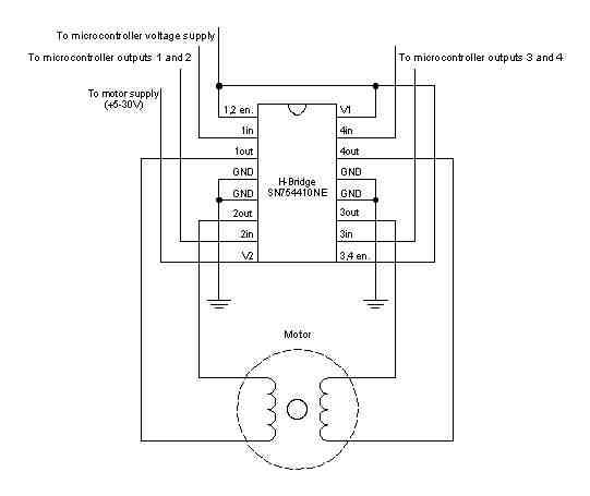
A stepper motor is a motor controlled by a series of electromagnetic coils. The center shaft has a series of magnets mounted on it, and the coils surrounding the shaft are alternately energized or de-energized, creating magnetic fields that...
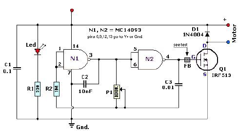
A quad 2-input NAND Schmitt trigger circuit can be designed using the MC14093 CMOS type IC, which serves as a simple pulse width modulation (PWM) controller electronic project. This PWM controller is straightforward and requires only a few external...
The Bong circuit is a high-frequency Colpitts oscillator that utilizes a Ge coil (L). It features two heads and is designed for simple production. The frequency of oscillation can be determined, and testing is conducted to ascertain the value...
It is well known that pests like rats, mice, etc., are repelled by ultrasonic frequency in the range of 30 kHz to 50 kHz. Human beings can't hear these high-frequency sounds. Unfortunately, all pests do not react at the...