
pest repellent circuit

The circuit operates by utilizing a combination of several integrated circuits and passive components to generate and modulate ultrasonic frequencies effectively. The core of the design is the CA3130 op-amp configured as a low-frequency square wave oscillator, which provides clock pulses to the CD4017 decade counter. The CD4017 outputs are used to control the frequency variation by enabling different resistive presets (VR2 to VR6) connected to the NE555 timer, which is configured in astable mode. The NE555 timer generates a high-frequency signal that modulates the output frequency of the circuit.
The D-type flip-flop (CD4013) takes the output from the NE555 and divides the frequency down to a symmetrical 40 kHz signal. This is crucial for driving the piezo tweeter effectively, as the tweeter requires a specific frequency range to emit ultrasonic sound waves. The push-pull transistor configuration (T1 to T4) amplifies this signal, ensuring that the output is powerful enough to repel pests effectively.
Adjustments can be made to the circuit using the variable resistor VR1, which controls the clock pulse rate, and the presets VR2 to VR6, which allow for fine-tuning of the ultrasonic frequencies emitted. The design's flexibility in frequency modulation makes it suitable for repelling various types of pests, as different species may react to different ultrasonic frequencies. The circuit can be tailored further by increasing the number of steps in frequency variation, enhancing its effectiveness in pest control applications. The option to connect a crystal transducer directly to the output without amplification provides an alternative for applications requiring lower power consumption while still operating within the desired frequency range.It is well know that pests like rats, mice etc are repelled by ultrasonic frequency in the range of 30 kHz to 50 kHz. Human beings can't hear these high-frequency sounds. Unfortunately, all pests do not react at the same ultrasonic frequency. While some pests get repelled at 35 kHz, some others get repelled at 38 to 40 kHz. Thus to increase the effectiveness, frequency of ultrasonic oscillator has to be continuously varied between certain limits.
By using this circuit design, frequency of emission of ultrasonic sound is continuously varied step-by-step automatically. Here five steps of variation are used but the same can be extended up to 10 steps, if desired. For each clock pulse output from op-amp IC1 CA3130 (which is wired here as a low-frequency square wave oscillator), the logic 1 output of IC2 CD4017 (which is a well-known decade counter) shifts from Q0 to Q4 (or Q0 to Q9). Five presets VR2 through VR6 (one each connected at Q0 to Q4 output pins) are set for different values and connected to pin 7 of IC3 (NE555) electronically.
VR1 is used to change clock pulse rate. IC3 is wired as an astable multivibrator operating at a frequency of nearly 80 kHz. Its output is not symmetrical. IC4 is CD4013, a D-type flip-flop which delivers symmetrical 40kHz signals at its Q and Q outputs which are amplified in push-pull mode by transistors T1, T2, T3 and T4 to drive a low-cost, high-frequency piezo tweeter. For frequency adjustments, you may use an oscilloscope. It can be done by trial and error also if you do not have an oscilloscope. This pest repeller would prove to be much more effective than those published earlier because here ultrasonic frequency is automatically changed to cover different pests and the power output is also sufficiently high.
If you want low-power output in 30-50 kHz ultrasonic frequency range then the crystal transducer may be directly connected across Q and Q outputs of IC4 (transistor amplifier is not necessary). 🔗 External reference
Related Circuits
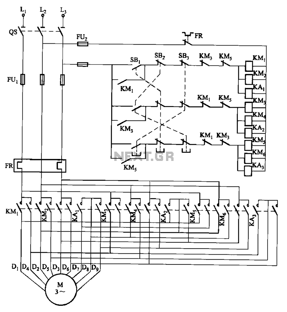
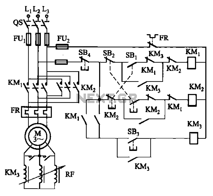
The circuit depicted in Figure 3-115 utilizes contactors and double buttons, allowing for speed conversion without the need to press the stop button. The buttons SBi, SBz, and SB3 correspond to high, medium, and low-speed operation, respectively. This circuit design...
Incorporate resistors in a parallel configuration to enhance audio input. To control the volume for each input channel, integrate a linear trimmer or potentiometer with the following configuration: pin 1 connects to ground, pin 2 serves as the output,...
The circuit is designed to provide protection to a DIY switching power supply for car amplifiers by shutting down under any or all of the three modes of protection (over voltage, under voltage and over temperature) with minimal components. The...
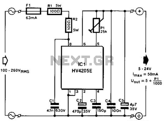
Direct derivation of 5 to 24 Vdc from AC mains without a transformer is possible with this circuit. Note that a direct mains connection to the DC output exists. Suitable safety precautions must be taken. This circuit design allows for...
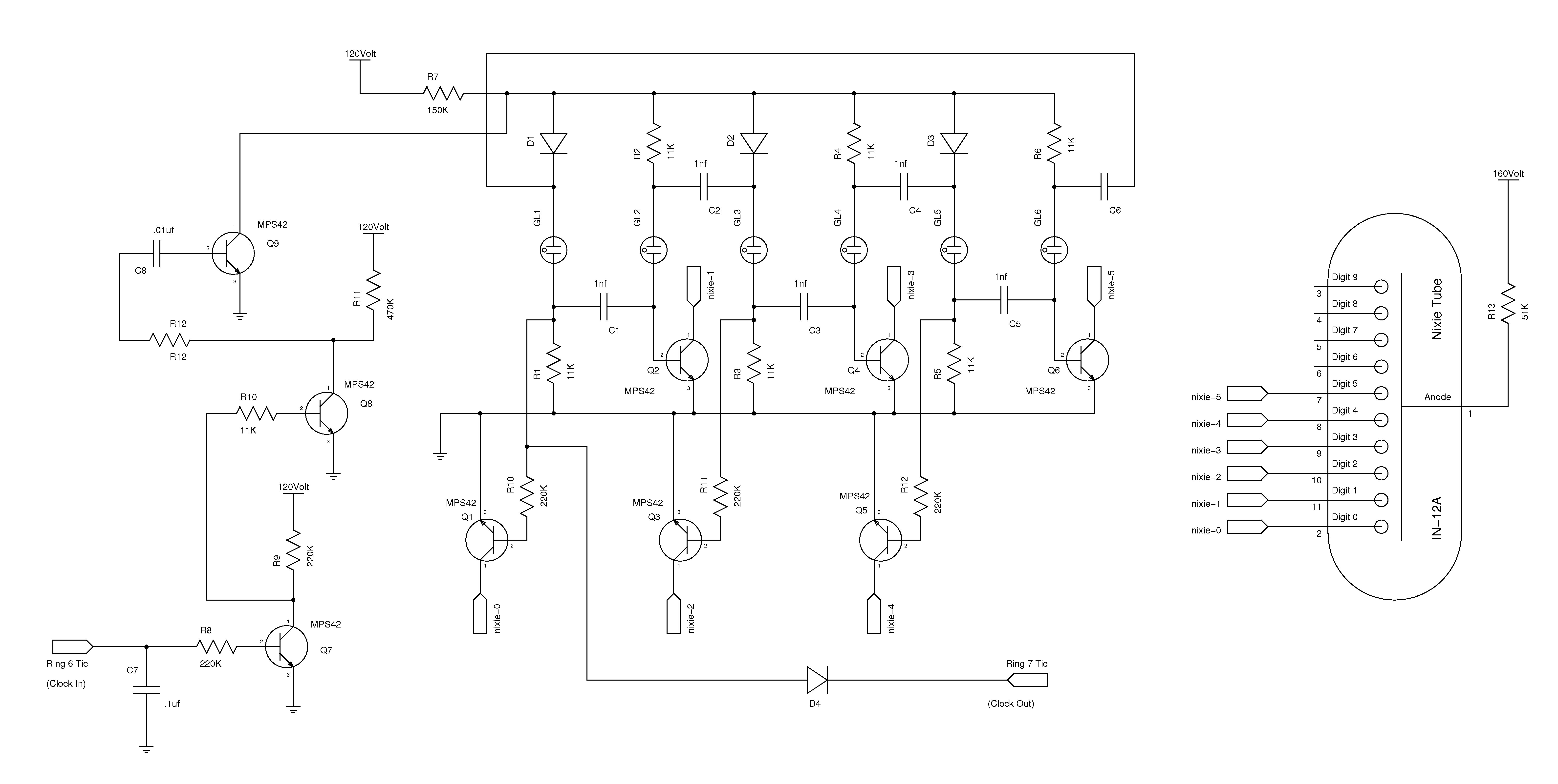
The nixie tube clock consists of a high-voltage power supply, seven ring counters, and an Atmel AVR processor. The power supply is shown in Schematic 1. It takes 12 volts AC and converts it to DC, which drives the...
The circuit illustrated in Figure 3-166 employs a button control mechanism. To initiate forward motion, the user presses button SB1, which activates the motor rotor through a frequency-sensitive rheostat (RF). As the motor speed approaches its rated speed, a...