
High-Power Alarm Driver Circuit

The presented circuit employs a low-powered SCR to control the activation of a higher-powered SCR, which is a common configuration in electronic control systems where isolation and amplification of control signals are required. The operation begins with the status change of switches S2, S3, S4, S5, S6, or S7. Each switch corresponds to specific operational conditions that dictate whether SCR1 or SCR2 will be triggered.
Upon the closure or opening of these switches, a corresponding SCR is activated, allowing current to flow through the circuit. The activation of either SCR1 or SCR2 leads to the conduction of current through diodes D1 and D2. These diodes are essential for protecting the circuit by ensuring that current flows in the correct direction, thus preventing any potential damage due to reverse polarity.
Resistor R5 plays a crucial role in this circuit by limiting the current flowing to SCR3. This is important for ensuring that SCR3 operates within its specified parameters, avoiding any risk of damage due to excessive current. Once SCR3 is triggered, it activates BZ1, which is a high-powered alarm designed to alert users of a specific condition. The interrupting type alarm indicates that it will produce sound or signal interruptions upon activation, providing immediate feedback regarding the circuit's state.
This configuration is particularly useful in applications such as safety systems, alarm systems, or any scenario where a low-power signal needs to control a more significant load. The combination of SCRs and diodes in this circuit effectively demonstrates the principles of controlled rectification and signal amplification, ensuring reliable operation in response to user inputs. In this circuit, a low-powered SCR is used to trigger a liigher powered SCR. When a switch is opening (S2, S3, S4) or closing (S5, S6, S7), either SCR1 or SCR2 triggers. This triggers SCR3 via Dl, D2, and R5. BZ1 is a high-powered alarm of the on interrupting type.
Related Circuits

SI and S2 must be pressed within 200 ms of each other to activate K1. The hold time is adjustable via K7. Additionally, the overlap time of SI and S2 can be modified by changing C1 and C2 or...
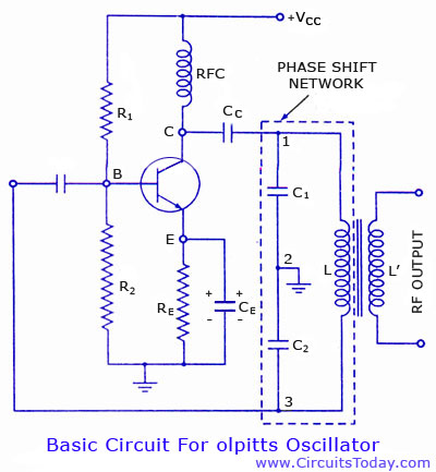
Colpitts oscillator circuit diagram and theory. Colpitts oscillator frequency equation. Colpitts oscillator using transistor. Colpitts oscillator using op-amp. The Colpitts oscillator is a type of electronic oscillator that generates sine waves and is widely used in various applications such as...
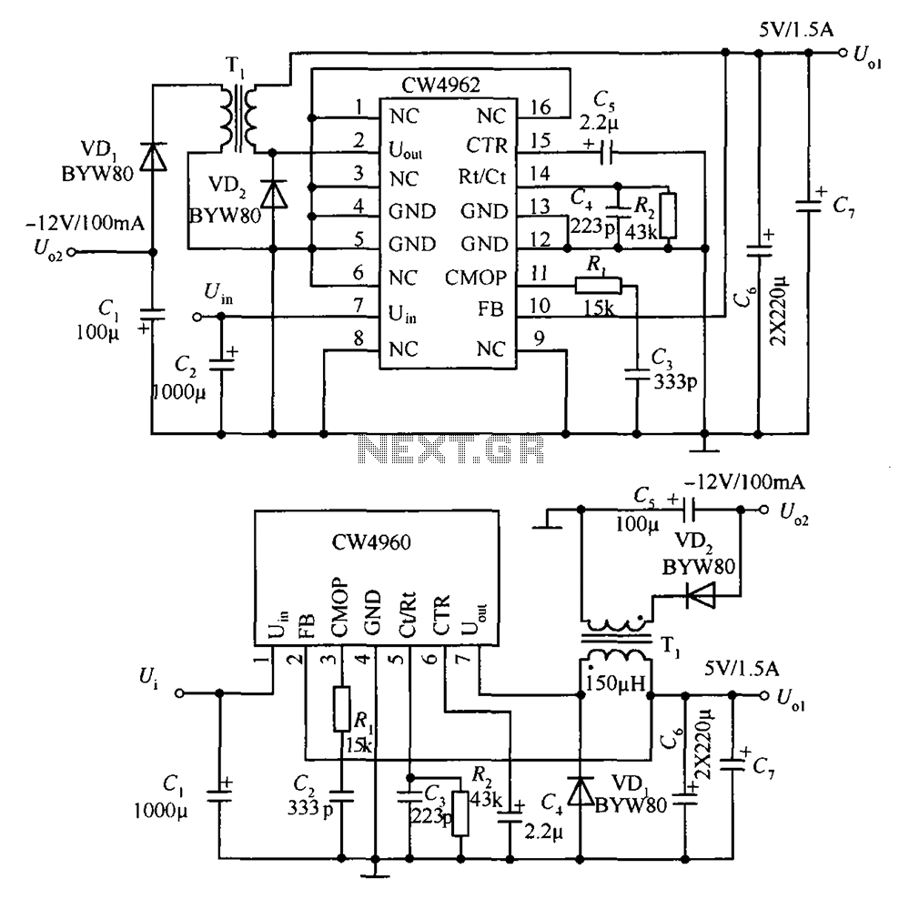
The circuit described is a stabilized power supply utilizing the CW4962 and CW4960 components, providing +5V at 1.5A and -12V at 100mA. The +5V output serves as the main power supply. The output circuit employs a transformer rather than...
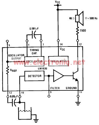
The LM1830 low-level detector can utilize an audio indication (speaker) or a visual indicator (LED - light-emitting diode) that activates when the level is too low. This low-level detector circuit generates a 500 Hz audio signal when the level...
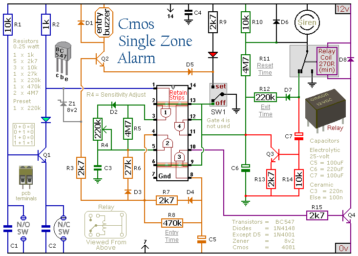
This circuit features automatic Exit/Entry delays, timed Bell Cut-off and System Reset. It has provision for normally open and normally closed switches and will accommodate the usual input devices such as Foil Tape, Pressure Mats, Magnetic Reed Contacts, Passive...
It is essential to consider migrating to PIC microcontrollers and exploring compilers such as those offered by Proton Smart, which include Sony IR and Philips RC5 codecs. This approach is particularly advisable for security-sensitive applications. Additionally, Bluetooth and Wi-Fi...