
10W Audio Amplifier with Bass-boost

This audio amplifier circuit is designed to deliver a power output of 10 watts, making it suitable for driving small speakers in various audio applications. The inclusion of a bass boost feature enhances low-frequency performance, providing a richer sound experience. The design is streamlined and does not require a preamplifier, which simplifies the overall circuit and reduces potential points of failure.
The core components of the circuit include a dual-gang 22K logarithmic potentiometer (P1), which allows for volume control and tonal adjustments. The dual-gang configuration enables independent control of two channels, ensuring balanced audio output for stereo applications.
In terms of layout, the circuit typically employs a class AB amplifier configuration, which balances efficiency and sound quality. Key components may include transistors or operational amplifiers, along with passive components such as resistors and capacitors to filter and stabilize the audio signal.
The bass boost feature is usually implemented through a combination of capacitive coupling and feedback mechanisms, allowing users to tailor the low-frequency response to their preferences. This can be achieved by adjusting specific capacitors in the feedback loop of the amplifier or through additional circuitry that selectively enhances bass frequencies.
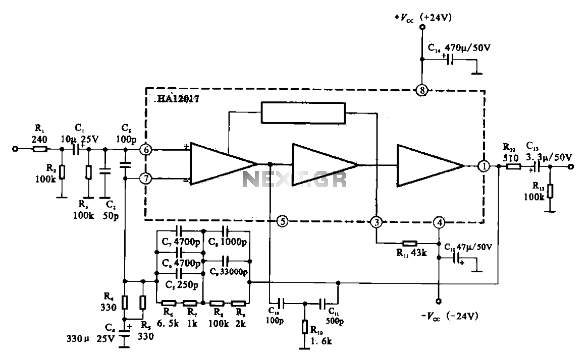
Overall, this 10W audio amplifier with bass boost is an excellent choice for hobbyists and professionals looking for a high-quality, straightforward solution for audio amplification needs. The design's simplicity and effectiveness make it a popular choice in various electronic audio projects.10W Audio Amplifier with Bass-boost. High Quality, very simple design. No preamplifier required. Circuit diagram: Parts: P1 22K Log.Potentiometer (Dual-gang for. 🔗 External reference
Related Circuits
Low-noise preamplifier circuit. This circuit demonstrates a typical low-noise preamplifier design, which can be utilized to amplify signals from sources such as magnetic heads and microphones within audio applications. The input signal is coupled through a capacitor and subsequently...
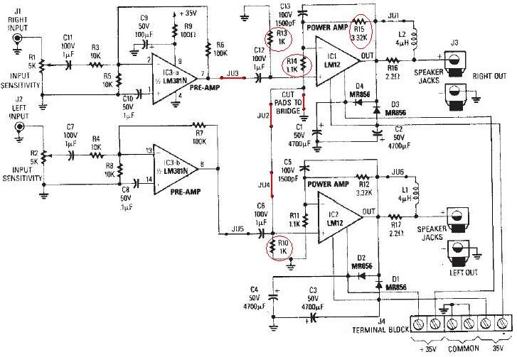
The LM12 audio amplifier circuit is designed to deliver high output power for loads with impedances of 4 ohms or 8 ohms. The maximum output power achievable by this amplifier is approximately 60 watts for a 4-ohm load and...
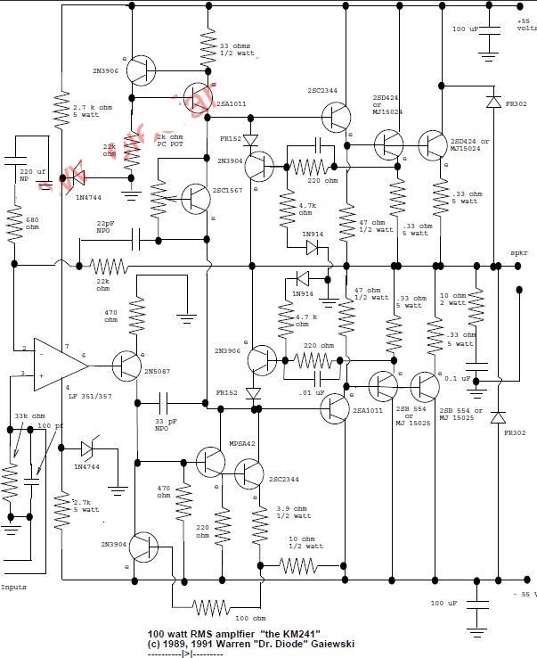
This is a 100-watt basic power amplifier designed to be relatively easy to build at a reasonable cost. It offers better performance, or musical quality, than the standard STK module amplifiers commonly found in mass-market stereo receivers. The design...
This single transistor audio mixer is utilized in an amplifier circuit design featuring a base-driven transistor, where the emitter is current-controlled. The majority of the driving current flows through the collector. This audio mixer circuit employs a single transistor to...
The TDA1308 is a Class AB headphone driver integrated circuit (IC) recently launched by Philips. Its primary features include a compact size and low power consumption, making it particularly suitable for portable CD players and other digital audio devices....
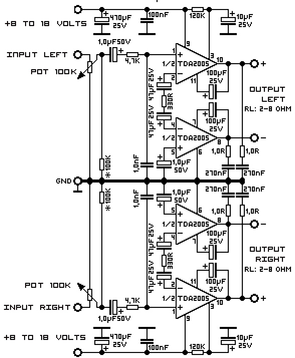
A 20W TDA2005 stereo amplifier designed for various applications, including the amplification of medium power speakers. It is suitable for automotive use; however, the power supply must be equipped with a choke of at least 150mH and should provide...