
10W Class D Power Audio Amplifier with TDA7480

The Class D audio power amplifier utilizing the TDA7480 is designed to deliver efficient audio amplification with a maximum output power of 10W, suitable for both 8Ω and 4Ω loads. This amplifier operates with a total harmonic distortion (THD) of 10%, which is a critical specification for maintaining audio fidelity in various applications, including home audio systems and portable devices.
The TDA7480 integrates a variety of features that enhance its performance, including built-in protection mechanisms against over-temperature and short-circuit conditions, ensuring reliable operation. The amplifier requires a split power supply, with a maximum voltage rating of ±20V, allowing for flexibility in system design and compatibility with various power sources.
In the schematic, the power stage of the amplifier is designed to efficiently switch the output transistors, minimizing power loss and enabling high-efficiency operation typical of Class D amplifiers. The input stage includes differential inputs to reduce noise and improve signal integrity. Feedback loops are implemented to stabilize gain and reduce distortion, contributing to the overall audio quality.
Additional components in the circuit may include filter capacitors to smooth the power supply and decoupling capacitors to reduce high-frequency noise. Input coupling capacitors are also utilized to block DC offsets from the audio source, ensuring that only the desired AC audio signal is amplified.
The layout of the circuit should be carefully considered to minimize electromagnetic interference (EMI) and ensure optimal thermal management. Proper grounding techniques and the placement of components can significantly impact the performance of the amplifier, making it essential to follow best practices in PCB design.
Overall, this Class D audio power amplifier schematic with the TDA7480 is a robust solution for high-efficiency audio amplification, providing a balance between power output, audio quality, and thermal performance.Class D audio power amplifier schematic diagram with TDA7480, capable of 10W output power at a load of 8w/4w and a total harmonic distorsion of 10%. Requires a split-supply (max. ±20V).. 🔗 External reference
Related Circuits
The preamp circuit is completely conventional, and by necessity is AC coupled throughout. The artificial earth is derived by two resistors (R1 and R2), which will set the "earth" at exactly 1/2 the supply voltage. This is nominally 13.8V...
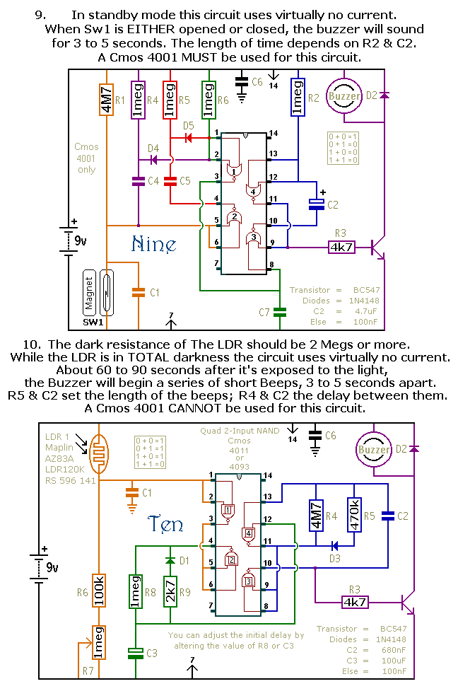
This document outlines a selection of small self-contained alarm circuits. Each alarm's main features are detailed on the circuit diagram. They are designed to have a very low standby current, making them suitable for battery operation. Each pair of...
This small amplifier was intended to be used in conjunction with an electric guitar to do some low power monitoring, mainly for practice, either via an incorporated small loudspeaker or headphones. The complete circuit, loudspeaker, batteries, input and output...
The ADP1864 is a compact, cost-effective, constant-frequency current-mode step-down DC-DC controller. It drives a P-channel MOSFET to regulate an output voltage as low as 0.8 V with ±2% accuracy, handling load currents up to 5 A from input voltages...
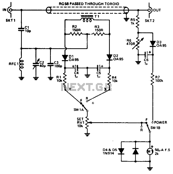
The reflectometer (SWR power meter) operates across three decades, ranging from 100 kHz to 100 MHz. It can be designed to handle RF power levels as low as 500 mW and up to 500 watts. The reflectometer, also known as...
This is a simple microphone preamplifier circuit that can be used between a microphone and a stereo amplifier. This circuit is suitable for connection with standard home stereo amplifier line/CD/aux/tape inputs. The microphone preamp can accommodate both dynamic and...