
110Db Beeper Circuit

The circuit design effectively utilizes the 74C14 CMOS IC to create a high-output audio signal suitable for applications requiring loud sound generation. The critical component, the piezoelectric device, is chosen for its ability to convert electrical energy into sound energy efficiently. The feedback mechanism is essential for maintaining the resonance of the piezoelectric element, ensuring that the generated sound is at its maximum loudness.
The astable oscillator configuration is fundamental in establishing a continuous oscillation at a frequency that is well-suited for the piezoelectric device. By setting the frequency to five times lower than the resonant frequency of 3.2 kHz, the circuit ensures that the piezoelectric element is driven effectively, allowing it to vibrate at its optimal operating point.
The differential drive configuration created by cross-wiring the inverter sections enhances the output voltage across the beeper, providing a robust sound output. This arrangement allows for an increase in the peak-to-peak voltage to about 18 V, significantly amplifying the sound produced by the piezoelectric device.
The inclusion of a second astable oscillator functioning at approximately 2 Hz introduces a modulation effect, which can be used to create a pulsing sound effect. The ability to gate the main oscillator on and off via a diode provides flexibility in sound output, allowing for variations in tone and duration. However, for applications requiring a steady tone, the modulation circuit can be omitted, simplifying the design while maintaining high sound output.
Overall, this circuit exemplifies a practical approach to generating high-decibel sound using a straightforward combination of CMOS technology and piezoelectric actuation, making it suitable for various audio signaling applications. This circuit will generate an ear-splitting 110 dB from 9 V. The setup uses a single 74C14 (CD40106B) CMOS hex inverting Schmitt-trigger IC, wliich must be used with a piezoelectric device with a feedback terminal. The feedback terminal is attached to a central region on the piezoelectric wafer. When the beeper is driven at resonance, the feedback signal peaks. One inverter of the 74C14 is wired as an astable oscillator, The frequency is chosen to be 5 times lower than the 3.2 kHz resonant frequency of the piezoelectric device.
Feedback from the third pin of the beeper reinforces the correct drive frequency to ensure maximum sound output. Four other inverter sections of the IC are wired to form two separate drivers. The output of one section is cross-wired to the input of the second section. The differential drive signal that results produces about 18-V p-p when measured across the beeper. The last inverter section is wired as a second astable oscillator with a frequency of about 2 Hz. It gates the main oscillator on and off through a diode. For a continuous tone, the modulation circuit can be deleted.
Related Circuits

A simple musical horn circuit designed for use in cars or motorcycles can be connected to the 12V battery of any vehicle. This circuit is commonly utilized as a reverse musical horn. It employs the low-cost musical integrated circuit...
Standard LED flashers activate the LED in a rapid on-off sequence, which can become bothersome over time. The circuit presented here offers a more gradual illumination effect. This circuit utilizes a simple design to create a soft flashing LED effect,...
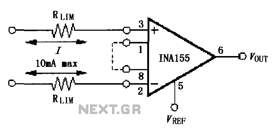
The input current protection circuit is illustrated in FIG, utilizing INA155/156. The INA155 features internal electrostatic discharge (ESD) protection diodes that become active when the input voltage exceeds the supply voltage by 500mV. In this scenario, the protection diodes...
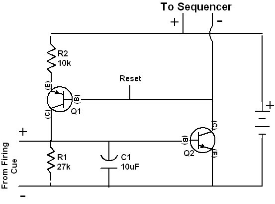
The 4017 integrated circuits are not initialized to a known state because the reset pins are not briefly forced high when the circuit is powered on. While the chips might typically power up in the normal reset condition, this...
These circuits could be used as the basis for Model Railroad DCC Boosters or PWM motor controllers. The first schematic is for a basic 3 Amp - DCC Booster using the LMD 18200 CMOS, H-Bridge. Included in the design...
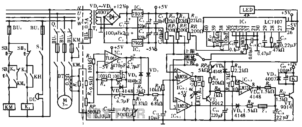
The circuit operates during standard inspection work by utilizing the voltage across resistor R2, which is connected to RP, to generate the input signal for IC4. Components R3 through Rg, along with capacitors C7 and C1, and diodes VD7...