
H-Bridge Motor Control Circuits

The described circuit serves as a foundational design for a Digital Command Control (DCC) booster, which is essential in model railroading for managing multiple trains on a single track. The use of the LMD18200 CMOS H-Bridge allows for efficient control of the motor's direction and speed, making it suitable for PWM (Pulse Width Modulation) applications.
The LMD18200 is a dual H-Bridge driver capable of delivering up to 3 Amperes of continuous output current per channel, which is adequate for driving small to medium-sized model train motors. The H-Bridge configuration enables the reversal of motor polarity, thus allowing for forward and backward motion control. This feature is crucial for model railroads where directional control of locomotives is required.
The inclusion of a 5V regulator in the design is significant as it ensures that the control circuitry, including the DCC signal generation and display components, receives a stable voltage supply. This is vital for the reliable operation of the DCC system, as fluctuations in voltage can lead to erratic behavior in the signal transmission to the locomotives.
In operation, the DCC booster takes a digital signal and converts it into a higher voltage suitable for driving the model trains. The PWM technique is employed to modulate the power delivered to the motors, allowing for precise speed control. This is achieved by rapidly switching the power on and off, effectively controlling the average voltage and current supplied to the motor.
Overall, this circuit design provides a robust solution for model railroad enthusiasts looking to implement advanced control systems for their layouts, enabling enhanced functionality and operational flexibility.These circuits could be used as the basis for Model Railroad DCC Boosters or PWM motor controllers. The first schematic is for a basic 3 Amp - DCC Booster using the LMD 18200 CMOS, H-Bridge. Included in the design is a 5Volt regulator that supplies power to the DCC signal generation and display circuitry. 🔗 External reference
Related Circuits
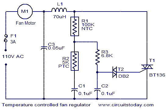
This fan regulator circuit automatically controls the speed of a fan based on temperature. It utilizes two thermistors (R1 and R2) for temperature sensing. The operation is similar to previously published designs, with thermistors replacing the potentiometer. As the...
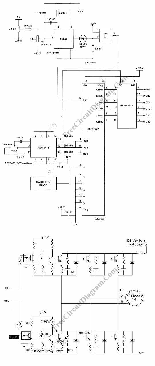
Controlling the speed of a three-phase AC motor is achieved by regulating the frequency of the power supply, as the motor operates in synchronization with the line. To control the speed of a three-phase AC motor, it is essential to...
It's basically a photovore with a couple tactile sensors. It's rather complex but can give neat behaviors with modifications to the circuit. At this point I don't have any plans to give more information on this circuit so your...
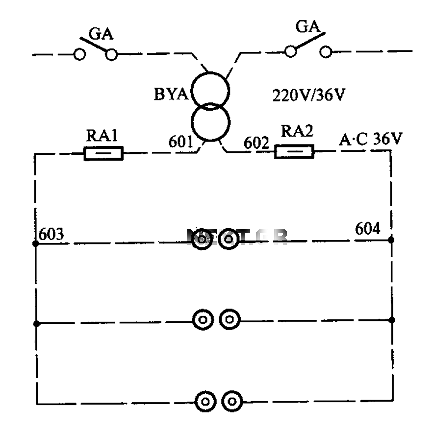
APM-81 lift includes the main circuit, safety circuit, and brake circuit. The APM-81 lift system is designed with a comprehensive electrical architecture that integrates a main circuit, a safety circuit, and a brake circuit, ensuring reliable operation and enhanced safety...
This circuit controls resistive and inductive loads up to 2,500W. Its primary component is the Siemens TLE3103 integrated phase control circuit, which includes its own power supply, a zero voltage crossing detector, and a logic driver. An additional feature...

Digital Command Control (DCC) provides significant advantages over traditional DC analog control systems, primarily due to its simplified wiring. DCC enables the individual control of multiple locomotives on the layout without requiring electrical isolation of track sections. The main...