
Musical Car Reverse Horn Circuit PCB

The circuit consists of several key components: a 12V battery, a 7805 voltage regulator, two diodes (D1 and D2), and the UM66 musical IC. The 7805 voltage regulator is essential for stepping down the voltage from 12V to a manageable level for the UM66. The output of the 7805 is typically 5V, but by using two silicon diodes in series, the voltage is reduced to approximately 3.8V, which is within the acceptable range for the UM66 to operate effectively.
The circuit's functionality is straightforward. When the vehicle's ignition is on, the switch connects the 12V battery to the circuit. The voltage regulator ensures that the UM66 receives the correct voltage, allowing it to generate musical tones. The diodes protect the UM66 from overvoltage conditions, which could damage the IC. The switch acts as a control mechanism; it must be pressed when the vehicle is in reverse to activate the musical horn, providing an audible alert to pedestrians and other vehicles.
For those with advanced skills in electronics, it is possible to modify the circuit to allow for automatic sound playback when the vehicle is in reverse. This would involve additional components such as a relay or a microcontroller to detect the reverse gear engagement and trigger the musical horn without the need for manual switching. Such modifications would enhance the functionality of the circuit, making it a more sophisticated solution for vehicle safety and awareness.Want to make some stuff that fits your car or motor cycle Then here is a simple musical horn circuit that can be connected to the 12V battery of any car or motorcycle. This circuit commonly used as reverse musical horn. Here we use a commercially very low cost musical IC UM66. But this Ic can only handle supply voltage below 4V. So we used a 7805 regulator ic for adjusting the voltage to 5V and its further reduced to 3. 8 volt by connecting two diodes D1 and D2 then it will supplied to musical horn producer UM66. Whenever we supply a 12v to the musical horn circuit, it will always produce music. So we need to connect a switch between battery and circuit and when you want to move on reverse gear, the switch must be pressed to produce music. ( You can setup the circuit to automatically plays sound while reversing the car but it requires more skill to implement)
🔗 External reference
Related Circuits
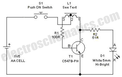
This simple LED driver circuit allows the operation of up to seven LEDs using a single NiMH (Nickel Metal Hydride) AA cell. The circuit generates voltage pulses. The LED driver circuit is designed to efficiently power multiple LEDs while maintaining...

This liquid detector circuit diagram is designed using common electronic components. The liquid detector can activate an active buzzer to produce sound when a certain water level is reached. Since the water sensor and control circuit for the buzzer...
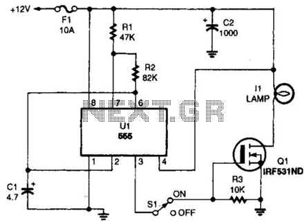
The headlight flasher is a 555 oscillator/timer configured as an astable multivibrator (oscillator). Its input is used to drive the gate of an IRF53IND hexFET, which acts as an on/off switch, turning the lamp on and off at an...
This is a classic design of a 35 W final amplifier utilizing two EL34 tubes in a push-pull configuration, developed by Siemens and Halske. The design dates back to March 24, 1953, and is identified by the code SV410/1....
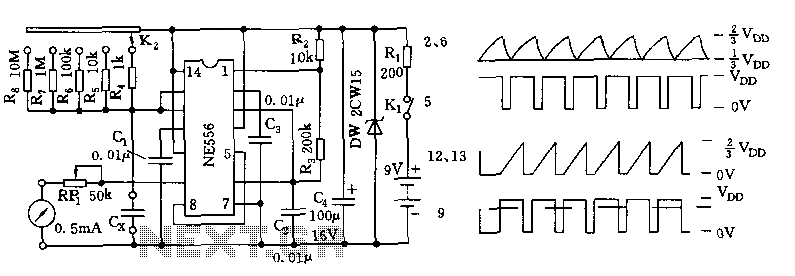
The tester comprises a dual time base circuit using a 556 timer and various RC components. The right side of the circuit features the 556 timer (556 1/2) along with resistors R2, R3, capacitors C2, C3, and additional components...
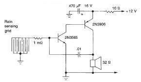
This rain detector electronic circuit project is a simple alarm circuit that activates an audio warning when liquid is detected on the sense pad. The circuit diagram is based on two transistors. When the sense pad conducts, transistors Tr1...