
12 to 120 Volt Inverter

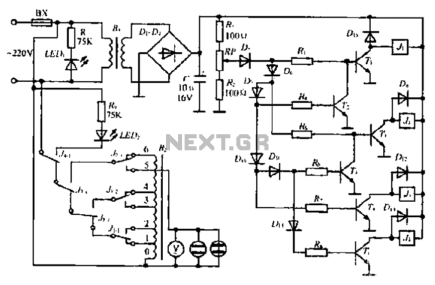
This circuit is designed to provide a robust 15 watts of AC power, suitable for a variety of small devices, including lamps, shavers, small stereos, and various small appliances. The output is configured as a square wave, which is typical for low-cost inverters and power supplies but may introduce some audible hum in sensitive audio equipment.
The circuit features an automatic shutdown mechanism to prevent damage from overcurrent conditions. This self-protection feature is critical for maintaining the integrity of both the circuit and the connected devices. When the load exceeds the specified limit, the circuit will automatically cease operation, thus safeguarding against overheating and potential failure.
To mitigate the hum associated with the square wave output, an adjustment to the output capacitor can be made. The current value is set at 0.47 µF, and increasing this value can help smooth the output waveform, thereby reducing the audible noise in connected audio devices. Care should be taken when selecting the capacitor to ensure it can handle the voltage and current levels present in the circuit.
The circuit utilizes high-power PNP transistors, which are essential for handling the output current required for the load. Recommended components for this application include the Radio Shack part number 276-2025 or the TIP32 transistor, both of which are capable of managing the thermal and current demands of the circuit.
Powering the circuit is a transformer rated at 24 volts and 2 amps. This transformer steps down the voltage and provides the necessary current to the circuit. It is important to ensure that the transformer is adequately rated for the maximum load to prevent saturation and overheating.
Overall, this circuit design effectively combines essential components to deliver reliable AC power while incorporating protective features to enhance longevity and performance. Proper component selection and configuration will ensure optimal operation across a range of small appliance applications.It will supply 15 watts of AC power to a device. It should power lamps, shavers, small stereos and small appliances. If you draw to much power the circuit will shut down all by itself. The output of this circuit is a square wave so there may be some noticeable hum on audio units plugged into it. To reduce some of the hum increase the value of the output capacitor which is at .47uf now. That transistor in the circuit are high power PNP transistors. Radio Shack part number 276-2025 are good ones to use or TIP32. The transformer is a 24 volt 2 amp c 🔗 External reference
Related Circuits
The inverter circuit diagram utilizing the NE555 timer is illustrated, designed to convert a +12V DC battery voltage into a 220V AC output voltage. In this circuit, the NE555 functions as an oscillator, with the oscillation frequency determined by...
The output current of the LM317T can be increased by incorporating an additional power transistor to share part of the total current. The current sharing is determined by a resistor connected in series with the input of the LM317...
A simple LED-based voltmeter is required to monitor the voltage of a variable power supply. The proposed LED voltmeter circuit utilizes a series of light-emitting diodes (LEDs) to visually represent the voltage level of a variable power supply. This...
A step-down transformer converts AC 220V to a lower voltage. A diode bridge rectifier and filter capacitor provide a direct current (DC) output, which fluctuates with variations in the grid voltage. A resistive voltage divider is used for sampling....
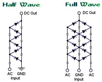
How to create a voltage multiplier using diodes and capacitors, capable of producing extremely high voltage. A voltage multiplier is a circuit that converts a lower AC or DC voltage into a higher DC voltage using a combination of capacitors...
If you want to try a higher voltage with your pedals, try this simple and easy voltage doubler circuit which uses an ICL7660 CMOS Voltage Converter Chip. I have found that JFETs such as the J201 sound much better...