
DIY Homemade Voltage Multiplier

A voltage multiplier is a circuit that converts a lower AC or DC voltage into a higher DC voltage using a combination of capacitors and diodes. The basic operation of a voltage multiplier involves charging capacitors through diodes during one half of the input cycle and discharging them through the load during the other half, effectively increasing the output voltage.
The most common type of voltage multiplier is the Cockcroft-Walton multiplier, which consists of a series of capacitors and diodes arranged in a ladder-like configuration. Each stage of the multiplier consists of one diode and one capacitor. The input voltage is applied to the first stage, where the capacitor charges to the peak input voltage. In subsequent stages, the capacitors charge to higher voltages, resulting in an output voltage that is a multiple of the input voltage.
To construct a voltage multiplier, the following components are typically required:
1. Diodes: High-voltage diodes capable of handling the peak reverse voltage.
2. Capacitors: High-voltage capacitors with appropriate capacitance values to store the charge.
3. Input Voltage Source: An AC or DC source that provides the initial voltage to the circuit.
The design can be scaled by adding more stages, with each stage increasing the output voltage. Care must be taken to ensure that the components used can withstand the high voltages produced, and proper insulation and safety measures should be implemented to prevent electrical hazards.
When designing a voltage multiplier circuit, the frequency of the input voltage source, the load resistance, and the capacitance values will affect the efficiency and performance of the circuit. The output voltage can be calculated based on the number of stages and the peak input voltage, making it a versatile solution for applications requiring high-voltage DC output.How to make a Voltage multiplier using dides and capacitors, capable of producing extreem high voltage.. 🔗 External reference
Related Circuits
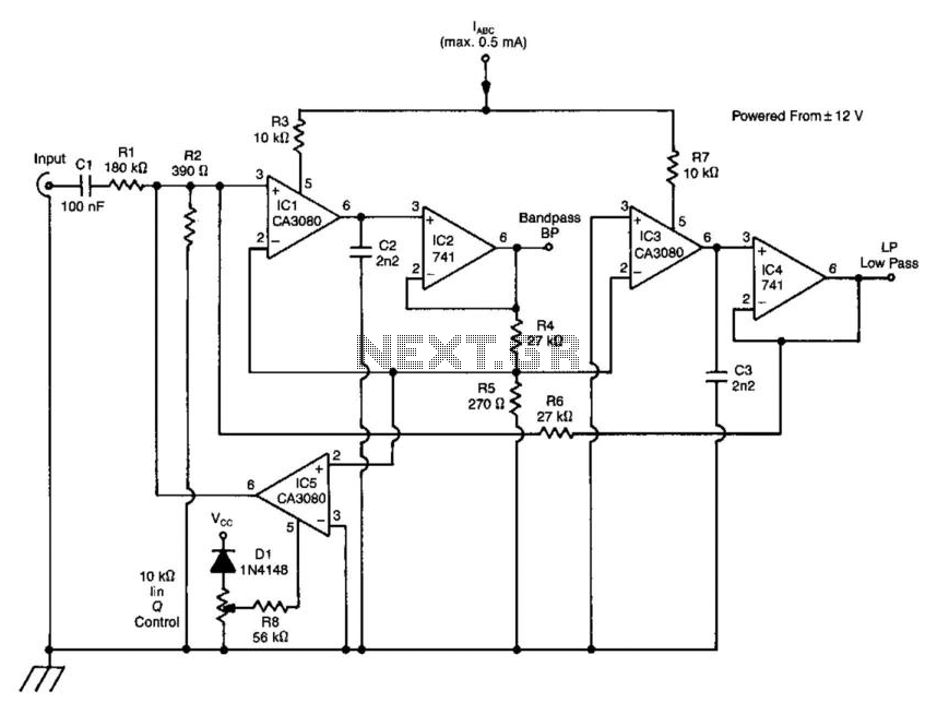
A standard dual integrator filter can be constructed using a few CA3080 operational amplifiers. By varying the parameters L, A, B, and C, the resonant frequency can be swept over a range of 1000:1. At IC1, three current-controlled integrators...
The LM3361A features a complete narrowband FM demodulation system that operates at supply voltages of less than 2V. The device includes several blocks such as an oscillator mixer, FM IF limiting amplifier, FM demodulator operational amplifier, scan control, and...
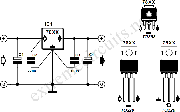
The voltage regulators from the 78xx series are commonly used in many analog power supplies. While it may seem unnecessary to elaborate on them due to their prevalence, it is beneficial to emphasize their key aspects. The 78xx series...
The Traynor YBA-1 is closely related to the classic Bassman/JTM-45 circuit. A vintage '67 model was acquired, which was in excellent condition except for a poorly executed reversible master volume modification and a burnt power transformer. This version features...
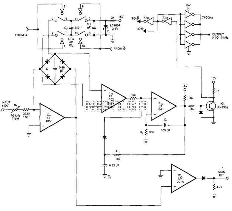
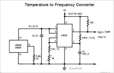
This voltage-to-frequency converter (VFC) accepts bipolar AC inputs. For -10 to +10 V inputs, the converter produces a proportional 0 to 10 kHz output. Linearity is 0.04%, and the temperature coefficient (TC) is approximately 50 ppm/°C. To understand the...
The voltage regulator integrated into the Arduino Uno is a linear-type regulator, which exhibits poor efficiency. When operating the ATmega238 at 5V with a 9V battery, nearly half of the battery's energy is wasted as heat by the regulator....