
12 V battery charger

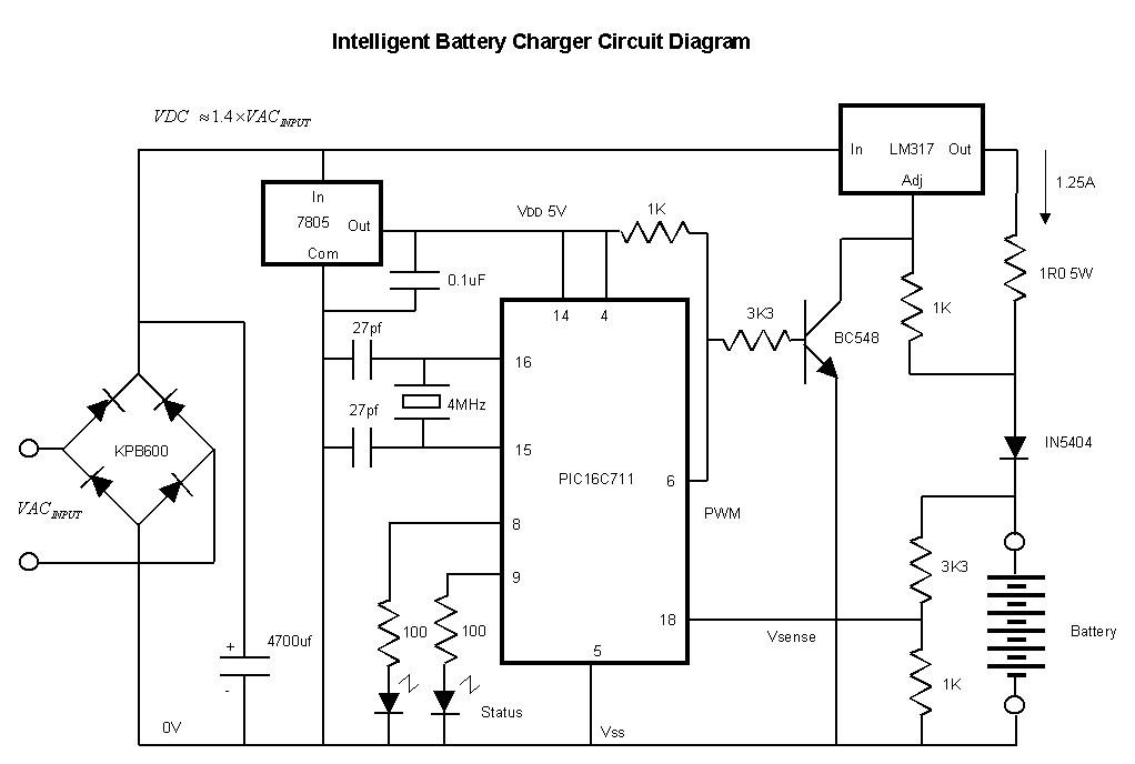
This high-performance charger circuit is designed specifically for gelled electrolyte lead-acid batteries, which are commonly used in various applications due to their reliability and efficiency. The circuit operates by initially supplying a constant current of 2A to the battery, ensuring a rapid recharge. This initial phase is crucial for quickly restoring the battery's capacity.
As the battery charges, its voltage increases, which in turn causes the charging current to decrease. This gradual reduction in current is essential for maintaining battery health and longevity. When the charging current falls to 150 mA, the circuit transitions to a float charging mode. This mode is characterized by a lower, stable output voltage that prevents overcharging, which can lead to battery damage.
The charger is activated by a start switch, which sets the output voltage to 14 V. This voltage is optimal for charging lead-acid batteries, ensuring effective energy transfer during the initial charging phase. As the battery approaches its full charge, the output voltage is carefully reduced from 14 V to approximately 12.5 V. This controlled decrease in voltage is critical for the safe termination of the charging process.
An important feature of this circuit is the use of a transistor (Q1) that serves as an indicator for the charging status. Once the battery reaches full charge, the LED connected to the transistor illuminates, providing a clear visual indication to the user. This feature enhances usability by allowing users to easily monitor the charging status without needing to measure the battery voltage directly.
In summary, this charger circuit combines efficient charging techniques with safety features to ensure the longevity and reliability of gelled electrolyte lead-acid batteries. Its automatic shut-off and visual indicators make it user-friendly and effective for various applications.This circuit is a high performance charger for gelled electrolyte lead-acid batteries. Charger quickly recharges battery and shuts off at full charge. Initially, charging current is limited to 2A. As the battery voltage rises, current to the battery decreases, and when the current has decreased to 150 mA, the charger switches to a lower float voltage preventing overcharge. When the start switch is pushed, the output of the charger goes to 14 V. As the battery approaches full charge, the charging current decreases and the output voltage is reduced from 14 V to about 12
5 V terminating the charging. Transistor Ql then lights the LED as a visual indication of full charge.
Related Circuits
Below is a comparator circuit that can measure the voltage of a car battery in steps of 1 volt. The voltage indication is achieved through comparison. The comparator circuit designed for measuring the voltage of a car battery utilizes an...
This affordable and simple-to-construct NiCd/NiMH battery charger is designed for the automatic charging of various batteries used in numerous applications. Reliable chargers are typically costly, while inexpensive chargers that come with original equipment often fail to charge cells correctly,...
Lead acid battery charger schematic using IC LM317. This lead acid battery charger circuit is simple to build and can be fit in a small box. The lead acid battery charger circuit utilizing the LM317 integrated circuit (IC) is a...
This simple circuit will find many applications as a battery eliminator for low power requirements. It consists of a transformer, a bridge rectifier and an electrolytic capacitor followed by a zener controlled series pass transistor. The output is stabilized...
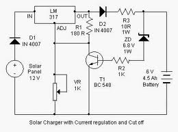
By adjusting the Adjust pin, the output voltage and current can be regulated. A variable resistor (VR) is connected between the Adjust pin and ground to achieve an output voltage of 9 volts to the battery. Resistor R3 limits...
This is another kit in our self-sufficiency range. We also have a 12v fluoro inverter kit for those who need to operate 20watt to 40watt fluorescent lamps from a 12v supply. We will be introducing a number of kits...