
Voltmeter With LED For Car Battery

The comparator circuit designed for measuring the voltage of a car battery utilizes an operational amplifier (op-amp) configured as a comparator. This circuit provides a simple yet effective means to monitor the battery voltage, ensuring that the vehicle's electrical system operates within safe parameters.
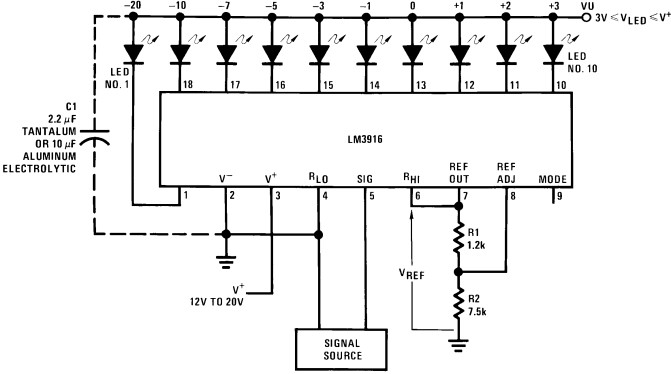
The circuit typically consists of an op-amp, a reference voltage divider, and an output indicator, such as an LED or a digital display. The reference voltage is set using resistors to create a series of voltage levels corresponding to the desired measurement increments (1 volt in this case). The car battery voltage is connected to the non-inverting input of the op-amp, while the reference voltage is fed into the inverting input.
As the battery voltage varies, the op-amp compares the input voltage from the battery against the reference voltage. When the battery voltage exceeds the reference level, the output of the op-amp switches states, activating the output indicator. This provides a visual representation of the battery voltage level. By designing multiple reference levels, the circuit can indicate different voltage ranges, allowing for a clear understanding of the battery's status.
For enhanced functionality, the circuit may include additional components such as hysteresis to prevent rapid switching of the output near the reference voltage thresholds, or a microcontroller for digital signal processing and more precise readings. This comparator circuit serves as a vital tool for monitoring car battery health and ensuring reliable vehicle operation.Below is a comparator circuit which is can measure with step of 1 volt, the voltage of car battery. The indication of voltage is done by comparison of .. 🔗 External reference
Related Circuits

This is a relay driver based on a PIC16F84A microcontroller. The board includes four relays, allowing control of four distinct outputs. The relay driver circuit utilizing the PIC16F84A microcontroller is designed for controlling multiple devices or systems through relay activation....
Convert the LEDs into LED bar graphs that display intensity. For instance, a song with a strong bass should cause the bar graph to rise to the maximum. The segments of the LED bar graph should consist of individual...

This is a simple and effective LED-based night lamp circuit that can be powered directly from a 230V mains supply. The circuit uses a total of 24 white LEDs and produces an output of approximately 15W. The resistor R1...
The SN75604, which features input control logic and requires only a single supply rail, can be utilized in light activation sensors and alarm drivers. The device's Vqq and enable inputs are connected to a voltage lead from the light...

The purpose of this circuit is to create a ring in which LEDs or lamps illuminate sequentially. Its main feature is high versatility; it can accommodate any number of LEDs or lamps, as each illuminating device has its own...
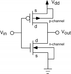
The fundamental issue presented is the perception that logic gates in a circuit seem to generate power from nothing, which contradicts the principles of physics. For instance, consider two NOT gates connected in series. It appears that the first...