
Stand-by Battery Charger

The circuit is designed to function as a battery eliminator, providing a stable output voltage of 7.5V for low power applications. The primary component, T1, is a transformer that steps down the mains voltage (230V AC) to a lower AC voltage (10V AC) suitable for the circuit's requirements. The output from the transformer is fed into a bridge rectifier formed by diodes D1 to D4 (1N4002), which converts the AC voltage to a pulsating DC voltage.
The pulsating DC is then smoothed by the electrolytic capacitor C1 (1000µF, 16V), which reduces the ripple voltage and provides a more stable DC output. Following this, a zener diode (D6, 8.2V, 0.4W) is used in conjunction with a series pass transistor (Q1, BD139) to regulate the output voltage. The zener diode ensures that the voltage remains stable at 7.5V by shunting excess voltage away from the output during normal operation.
In the event of a mains power failure, the circuit includes a standby battery (B1, 5x1.5V) connected in series with diode D7. This diode allows the battery to take over and supply power to the load while preventing backflow into the circuit. The voltage drop across D7 reduces the effective output voltage to approximately 7V when the battery is supplying power.
Resistor R3 serves a dual purpose; it is used to trickle charge the standby battery when the circuit is powered by mains. The proper value of R3 can be calculated by determining the voltage difference between the zener voltage and the battery voltage, then dividing this by the desired trickle charging current, which is approximately 0.7 mA.
The complete part list includes resistors (R1, R2, R3) rated at 1k ohm, a red LED (D5), a 50mA fuse (F1), capacitors (C1, C2 rated at 1000µF and 100µF respectively), the zener diode (D6), the transistor (Q1), diodes (D1 to D4 and D7), and the transformer (T1). This configuration provides a reliable power supply solution for low power electronic devices, effectively eliminating the need for a conventional battery while ensuring seamless operation during power outages.This simple circuit will find many applications as a battery eliminator for low power requirements. It consists of a transformer, a bridge rectifier and an electrolytic capacitor followed by a zener controlled series pass transistor. The output is stabilized at +7.5V. The stand-by battery, 7.5V, in series with D7, floats across the output terminals, ready to take over in case of main failure.
The voltage drop across D7 will then reduce the power supply to about 7V. The R3 has an additional function, when working off the mains it will trickle charge the dry cells or storage battery. It?s correct resistance can be found by dividing the voltage potential difference between the zener D6 and the battery by the safe trickle current, which may amount to some 0.7 milliamps.
Part List R1-2-3=1Kohm D5=Led Red 3mm F1=50mA Fuse C1=1000uF 16V D6=8V2 0.4W zener B1=5X1.5V Battery C2=100uF 16V Q1=BD139 D1...4-7=1N4002 T1=230Vac// 10Vac - 0.5A transform. 🔗 External reference
Related Circuits
In appliances that require alternating current, NiCad (NiCd) rechargeable batteries still demonstrate significant performance advantages compared to NiMH and lithium batteries. The charger circuit is critical in handling incorrect polarity of the battery placement. The core of this battery...
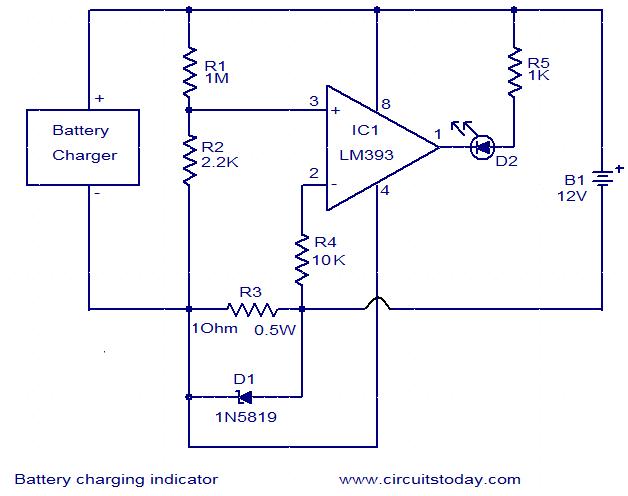
This simple circuit can be used to monitor whether a battery is charging. The voltage comparator IC LM393 is the core component of this circuit. The LED D1 will remain ON whenever there is at least 25 milliampere current...
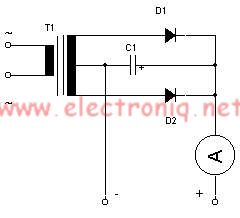
This simple lead-acid battery charger requires a center-tapped transformer (12V 0V 12V) capable of delivering a current of 5 amperes, two diodes, and one capacitor. To charge the batteries, the positive and negative terminals from the charger must be...
The circuit is a comparator that measures the voltage of a car battery in steps of 1 Volt. The voltage measurement is performed by comparing the battery voltage, applied to the inverting inputs of amplifiers, against reference voltages produced...
This design integrates power-on and low-battery indication features, capable of operating with any battery voltage up to 15V. It exhibits a very low current drain of 2mA or less. The circuit design incorporates a power-on indicator that activates when the...
FET Q1 functions as a constant current generator, providing biasing for LED D1 and the base of Q2. This configuration ensures that D1 emits light at a consistent intensity, regardless of the battery voltage, which ranges from 3 to...