
12 v nicad battery charger 200mah

The circuit for a 12V NiCad battery charger designed to supply a current of 200mA/h typically includes several key components to ensure safe and efficient charging. The main components include a transformer, a rectifier, a voltage regulator, and a current limiting resistor.
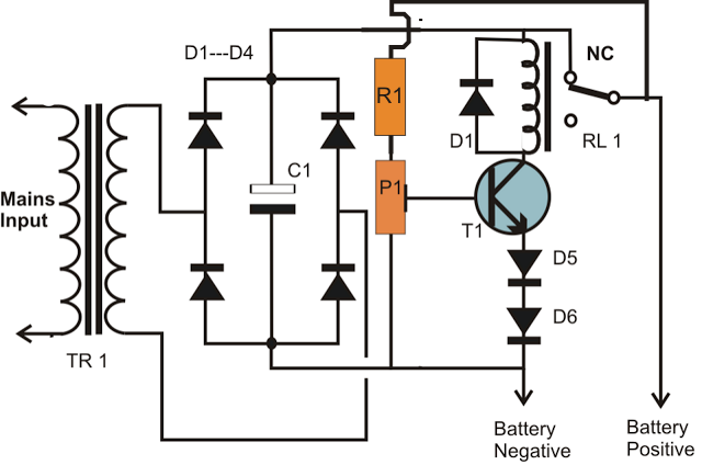
1. **Transformer**: The transformer steps down the AC mains voltage to a lower AC voltage suitable for charging a 12V battery. A transformer with a secondary voltage rating of approximately 12V-15V is commonly used to account for voltage drops in the subsequent components.
2. **Rectifier**: Following the transformer, a bridge rectifier is employed to convert the AC voltage into DC voltage. The bridge rectifier consists of four diodes arranged in a bridge configuration, allowing current to flow in one direction and providing a full-wave rectification. This results in a pulsating DC output.
3. **Smoothing Capacitor**: To reduce the ripple voltage from the rectified output, a smoothing capacitor is connected in parallel with the output. This capacitor stores charge and releases it when the voltage dips, providing a more stable DC voltage to the battery.
4. **Voltage Regulator**: A voltage regulator is often included to maintain a consistent output voltage, ensuring that the battery is charged safely without exceeding its voltage rating. A linear voltage regulator, such as the LM7812, can be used to regulate the output to approximately 12V.
5. **Current Limiting Resistor**: To prevent overcharging and to control the charging current, a current limiting resistor is implemented in series with the battery. The resistor value is calculated based on the desired charging current (200mA) and the voltage drop across the resistor.
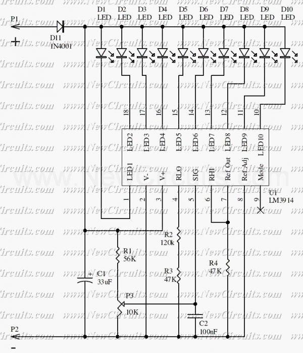
6. **LED Indicator**: An LED may be included in the circuit to indicate the charging status. This LED can be connected in parallel with the battery or in series with a resistor to limit current, providing visual feedback when the charger is active.
7. **Protection Diodes**: To protect the circuit from reverse polarity and potential damage, protection diodes can be added. These components ensure that if the battery is connected incorrectly, the circuit remains unharmed.
The overall design of the 12V NiCad battery charger should adhere to safety standards, including proper heat dissipation for components that may generate heat during operation. Additionally, it is essential to ensure that the circuit is compact and efficient for practical use in battery charging applications.12V Nicad Battery charger 200mA/H power supply. Go to that page to read the explanation about above power supply related circuit diagram. 🔗 External reference
Related Circuits
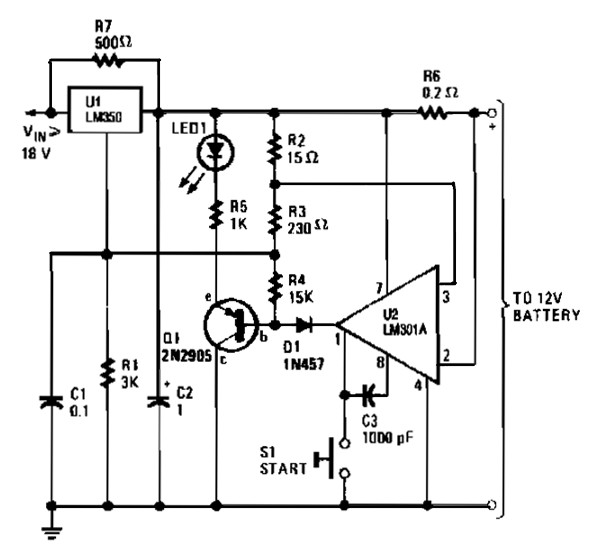
The gelled lead-acid battery charger circuit diagram enables rapid charging of gelled lead-acid batteries and automatically shuts off upon reaching full charge. Initially, the charging current is maintained at 2 A; however, as the battery voltage increases, the current...
This is a simple NiCd battery charger powered by solar cells. A solar cell panel or an array of solar cells can charge a battery at more than 80% efficiency. The described circuit functions as a basic NiCd battery charger...
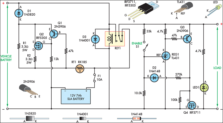
The SLA battery is charged from the vehicle's battery. When the engine is running, the voltage remains fairly constant, which greatly simplifies the charging circuit. If the SLA battery is fully charged, any further charging current from the vehicle...
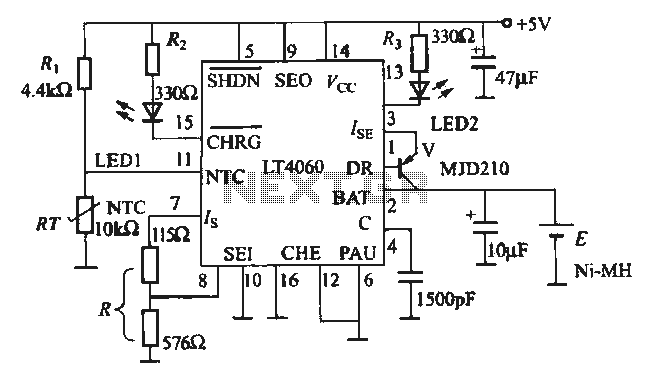
The charging circuit is designed for rechargeable batteries, particularly for situations where high charging currents can lead to increased temperatures. The LTC4060 includes an external thermistor that detects the charging temperature to prevent overheating. This device operates as a...
A simple battery charger circuit is described, utilizing a single transistor for voltage detection and automatically disconnecting the battery from the supply when fully charged. The circuit's high voltage trip point is set to switch off the charging voltage...
This simple circuit makes it possible to monitor the charging process to a higher level. Final adjustments are simple and the only thing needed is a digital voltmeter for the necessary accuracy. Connect an input voltage of 12.65 volts...