
high performance gelled lead acid charger

The gelled lead-acid battery charger circuit is designed to efficiently charge gelled lead-acid batteries while ensuring safety and prolonging battery life. The circuit typically includes several key components: a transformer, a rectifier, a voltage regulator, and a microcontroller or comparator for charge control.
The transformer steps down the AC voltage from the mains supply to a lower AC voltage suitable for charging the battery. The rectifier converts the AC voltage to DC, which is necessary for charging the battery. Common rectifier configurations include full-wave or bridge rectifiers, which provide a smoother DC output.
The charging current is initially set to 2 A, which is suitable for most gelled lead-acid batteries. As the battery charges, its voltage rises, and the circuit is designed to reduce the current accordingly to prevent overcharging. This can be achieved using a current sensing resistor and a feedback loop that adjusts the output based on the battery's voltage level.
A microcontroller or an operational amplifier can be employed to monitor the battery voltage. Once the battery reaches its full charge voltage, the circuit automatically turns off the charging current. This feature is crucial for maintaining battery health and preventing damage due to overcharging.
In addition to the basic components, the circuit may also include protection features such as fuses, thermal cutoffs, and voltage clamping devices to safeguard against overcurrent and overheating conditions. The overall design prioritizes efficiency and reliability, making it suitable for various applications where gelled lead-acid batteries are used, such as in renewable energy systems, backup power supplies, and electric vehicles.
For further insights and detailed explanations regarding this circuit and its applications, refer to the original source on the high-performance gelled lead-acid charger power supply.Gelled lead acid battery charger circuit diagram allow quickly charges gelled lead-acid batteries, and automatically turns off at full charge. First, the charge current is held at 2 A, but as battery voltage rises, the current will decreases. The schematic diagram come from circuit: High Performance Gelled lead acid charger power supply. Go to that page to read the explanation about above power supply related circuit diagram. 🔗 External reference
Related Circuits
The charger described in this article can charge packs of 4 to 7 cells with capacities ranging from 600mAh to 2Ah. The charger automatically begins charging when a pack is connected. It charges at a (nearly) constant current (adjustable),...
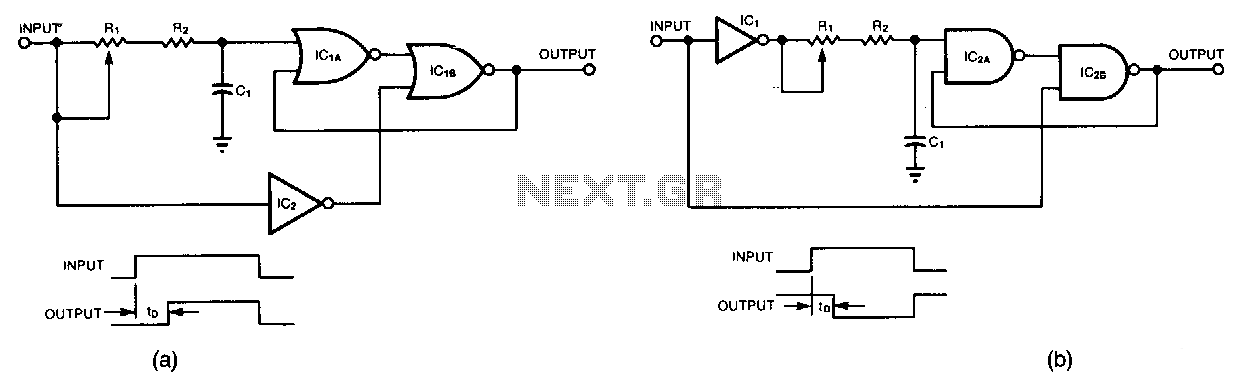
Circuit (a) delays the leading edge of a positive pulse while leaving the trailing edge nearly unaffected. A positive input transition, inverted by IC2, does not impact IC1B. However, when the positive transition reaches IC1A, delayed by the adjustable...
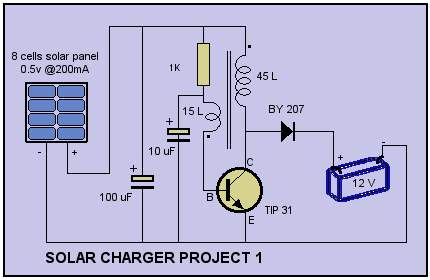
Solar Cell Charger Schematic. The circuit was built with a single oscillator system (blocking oscillator). The solar cell charger schematic utilizes a blocking oscillator configuration to efficiently convert solar energy into electrical energy suitable for charging batteries. This circuit typically...
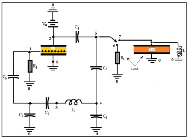
COMSOL's integration of SPICE® elements into its finite element method (FEM) allows for direct modeling of oscillators. In this approach, the triode and load are described using FEM, while all other circuit components are simulated with SPICE®. This modeling...
This project is one for the experimenter, but as shown will work extremely well. The sensing circuit can be made so sensitive that a load of only 2.5mA is enough for the circuit to detect, and disconnect the charger....
The circuit utilizes an inverting operational amplifier configuration with discrete transistors to address issues such as inadequate slew rate, significant distortion, and elevated noise levels. The output stage is powered by a constant current source, which is biased using...