
12 vdc to 240 vac inverter

The inverter circuit described is designed to convert a 12 VDC input into a 240 VAC output without relying on specialized components like toroidal transformers. Instead, it may employ a simpler architecture, possibly utilizing a standard transformer or a switching method to achieve the necessary voltage conversion.
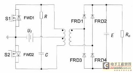
The circuit typically consists of a power stage, which could include MOSFETs or IGBTs for efficient switching, and a control circuit to manage the operation of these switches. The control circuit may generate a pulse-width modulation (PWM) signal to regulate the output voltage and maintain a stable AC waveform.
To ensure proper operation, the design must include protective elements such as fuses or circuit breakers to prevent overcurrent conditions. Additionally, filtering components, such as capacitors and inductors, may be necessary to smooth the output waveform and reduce electromagnetic interference (EMI).
The output stage may also incorporate feedback mechanisms to monitor the output voltage and adjust the PWM signal accordingly, ensuring that the inverter maintains the desired output voltage under varying load conditions.
Overall, this inverter circuit represents a practical solution for applications requiring AC power from a DC source, leveraging standard components while maintaining efficiency and reliability.This 12 VDC to 240 VAC Inverter circuit are not using special components such as the torodial transformer found in many inverters circuit.. 🔗 External reference
Related Circuits
With the increase in the variety of modern electrical equipment for vehicles and the rise in power levels, there is a growing demand for different types of power supplies, including AC and DC sources. The power system needs to...
Any step-down DC-DC converter can be utilized as an inverter without modifications to the operating schematic. The only differences between the standard step-down application and the inverting operation are the labels of the connection points. The step-down VOUT is... A...
Various values of D3 can be utilized to achieve different output voltages ranging from approximately 0.6V to around 30V. It is important to note that at elevated voltages, the circuit's performance may diminish, potentially resulting in lower current output....
An inverter is introduced which primarily utilizes a MOS field-effect transistor in conjunction with a conventional power transformer. The output power of the inverter is determined by the specifications of both the MOS field-effect transistor and the transformer, thereby...
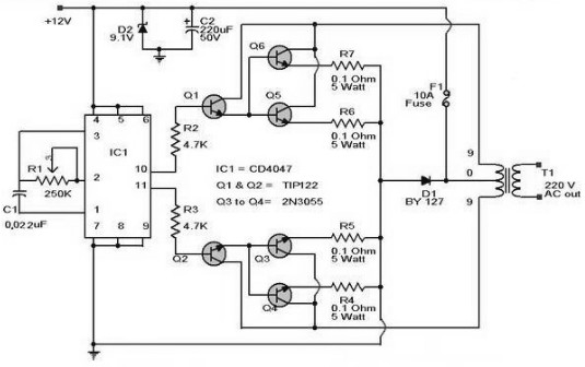
The schematic diagram of a 100W inverter circuit converts a 12V DC input to a 220V AC output. The circuit is built using the CD4047 integrated circuit, which generates a sine wave signal at 50Hz. The power transistor 2N3055...
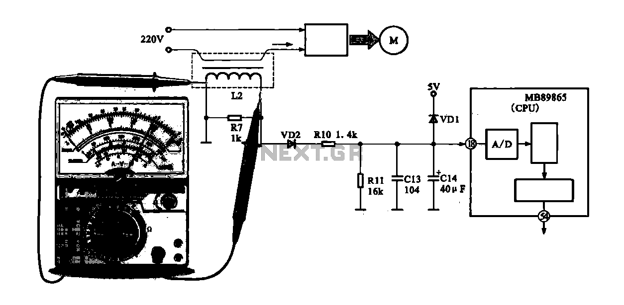
A current-voltage conversion circuit is commonly utilized in current detection applications. An example is the current detection circuit for a ring inverter air conditioner, which primarily serves to monitor the supply current of the compressor motor. Excessive current can...