
12 Volt 30 Amp PSU

The circuit described involves a voltage regulation system that utilizes a 7812 linear voltage regulator, which is designed to output a stable 12 volts. The input stage can be powered either by a transformer or a pair of car batteries, with the transformer being the more costly option. When using a transformer, it is essential to select one that can provide an input voltage significantly higher than 12 volts to account for the dropout voltage of the 7812 regulator, which typically requires at least 2-3 volts above the output voltage for proper regulation.
In a transformer-based design, an AC voltage is stepped down to an appropriate level, followed by rectification using diodes. The rectifier diodes must be rated for high peak forward current, ideally capable of handling 100 amps or more to ensure reliability under load conditions. This high current rating is crucial as the system may experience transient loads that can momentarily exceed the normal operating current.
The 7812 regulator itself has a limited output capacity, generally providing a maximum of 1 amp. To accommodate higher current demands, additional pass transistors are utilized in conjunction with the 7812. These transistors are configured to share the load current, allowing the circuit to deliver more than 1 amp to the output while maintaining the desired voltage regulation. The design must ensure proper thermal management for both the 7812 and the pass transistors, as they will dissipate heat during operation, especially under higher load conditions.
Overall, this configuration emphasizes the importance of selecting appropriate components, particularly the transformer and rectifier diodes, while also ensuring adequate heat dissipation and current handling capabilities for reliable performance in powering devices that require a stable 12V supply.The input transformer is likely to be the most expensive part of the entire project. As an alternative, a couple of 12 Volt car batteries could be used. The input voltage to the regulator must be at least several volts higher than the output voltage (12V) so that the regulator can maintain its output. If a transformer is used, then the rectifier diodes must be capable of passing a very high peak forward current, typically 100amps or more.
The 7812 IC will only pass 1 amp or less of the output current, the remainder being supplied by the outboard pass transistors. 🔗 External reference
Related Circuits
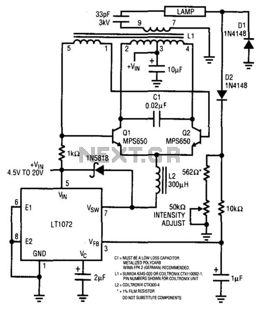
For backlit LCD displays, this supply will drive a lamp. The LT1072 drives Q1 and Q2, while a sine wave appears across C1. L1 is a transformer that steps up this voltage to approximately 1400 V. D1 and D2...
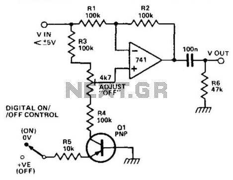
When transistor Q1 is switched off, the circuit operates as a voltage follower. By applying a positive voltage to the emitter of Q1 through a 10 kΩ resistor, the transistor is activated and enters saturation. Consequently, the lower end...
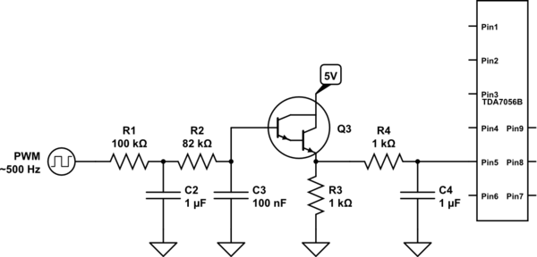
A voltage between 0.4 and 1.2 V is required on pin 5 to control the gain. In the initial two versions of the circuit, logic ICs and/or counters were utilized along with an operational amplifier and a resistor network...
To celebrate the hundredth design posted to this website and to fulfill the requests of many correspondents wanting an amplifier more powerful than the 25W MosFet, a 60 - 90W high-quality power amplifier design is presented here. The circuit...
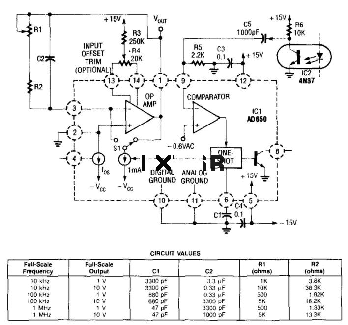
In this circuit, the input from the IC2 optocoupler is connected to the comparator input of the AD650 (Analog Devices or Maxim Electronics) voltage-to-frequency (V/F) converter. This converter internally generates a pulse that is sent to the operational amplifier,...
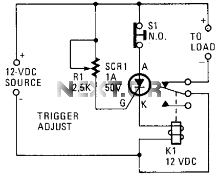
A silicon-controlled rectifier (SCR) is connected in parallel with the 12-V line and linked to a normally-closed 12-V relay, designated as K1. The gate circuit of the SCR is utilized to monitor the applied voltage. While the applied voltage...