
Frequency/Voltage Converter With Optocoupler Input

The circuit utilizes an optocoupler (IC2) to isolate the input signal from the rest of the system, ensuring that noise and voltage spikes do not adversely affect the performance of the V/F converter. The AD650 is a precision voltage-to-frequency converter that translates an analog voltage into a frequency output. Its comparator input receives the signal from the optocoupler, which allows for accurate detection of the input voltage level.
Upon receiving the signal, the AD650 generates a pulse train whose frequency is directly proportional to the input voltage. This pulse train is then fed into an operational amplifier (op-amp), which is configured to convert the frequency signal into a corresponding DC voltage. The output voltage of the op-amp reflects the frequency of the input signal, thus providing a linear relationship between the input voltage and the output voltage.
Component values, such as resistors and capacitors, play a crucial role in determining the response time, bandwidth, and stability of the circuit. These values should be selected based on the desired frequency range and the specific application requirements. The schematic diagram accompanying this description provides a visual representation of the circuit layout, including the connections between the optocoupler, V/F converter, and operational amplifier, as well as the values of the components used in the design.
This configuration is commonly employed in applications where it is necessary to convert an analog signal into a frequency output, such as in frequency modulation systems, data acquisition systems, and various control applications. The reliability and performance of the circuit can be enhanced through careful selection of components and proper circuit layout techniques. In this circuit, the input from IC2 optocoupler is fed to the comparator input of the AD 650 (Analog Devices or Maxim Electronics) V/F converter. This internally generates a pulse that is fed to the op amp, which outputs a dc voltage that is proportional to frequency. Component values are shown in the figure.
Related Circuits
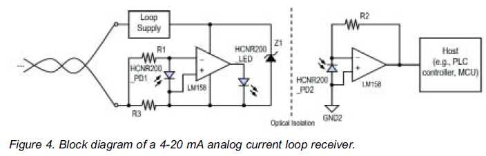
High linearity analog optocouplers offer the versatility needed to address a variety of analog isolation requirements. For high voltage applications, these optocouplers can effectively transmit analog signals between high voltage and low voltage areas without introducing distortion. This article...
This circuit is a high input voltage regulator that generates a voltage of 5V. In this circuit, the input voltage for the LM340 must remain within the limits specified in the datasheet. Operating the device above the absolute maximum...
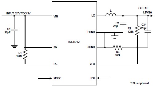
The ISL8012 is a high-efficiency, monolithic, synchronous step-down DC-DC converter that can be designed into a simple electronic project. It supports a maximum continuous output current of up to 2A from an input supply range of 2.7V to 5.5V....
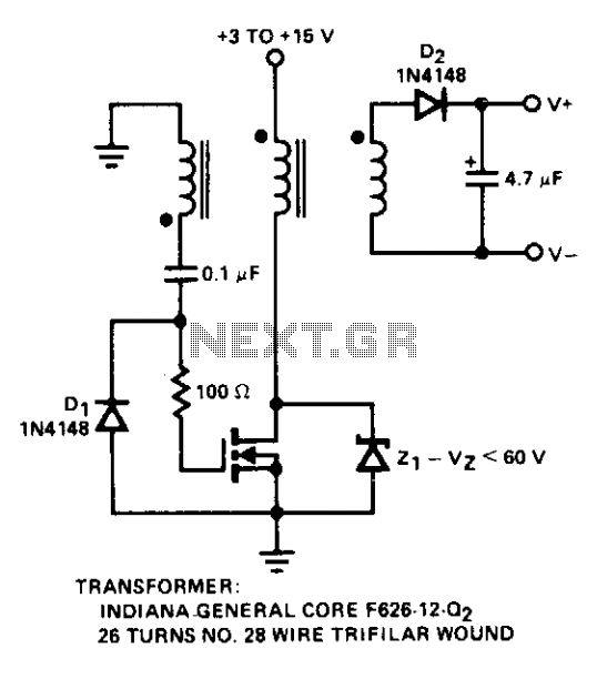
Diode D1 prevents negative spikes from occurring at the MOSFET gate. The 100-ohm resistor acts as a parasitic suppressor, while Z1 functions as a dissipative voltage regulator for the output and clips the drain voltage to a level below...
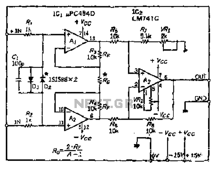
All resistance values are equal, resulting in the Cantonese operational amplifier's gain (A) being equal to 1. However, by selecting smaller resistances, the gain can be adjusted. The circuit can achieve the desired gain through six configurations. Two heavy...
This circuit facilitates a VGA to SCART connection, converting VGA signals into RGB and composite sync signals suitable for a TV via a SCART connector. The RGB components—Red, Green, and Blue—output from the VGA card are already at the...