
12 Volts Lead Acid Battery Charger

This 12-Volt lead-acid battery charger circuit is designed to efficiently charge and maintain the battery's voltage level, ensuring optimal performance and longevity. The charger typically consists of several key components: a transformer, a rectifier, a voltage regulator, and various passive components such as resistors and capacitors.
The transformer steps down the mains voltage to a lower AC voltage suitable for charging the battery. The output from the transformer is then fed into a bridge rectifier, which converts the AC voltage into DC voltage. This rectified output is not yet suitable for charging the battery directly, as it may vary and could exceed the battery's maximum voltage rating.
To achieve a constant charging voltage, a voltage regulator is employed. This component stabilizes the output voltage to a safe level (typically around 13.8 to 14.4 volts for a 12-volt lead-acid battery) to ensure that the battery is charged without overcharging, which can lead to reduced battery life and potential hazards.
Additional components may include diodes for reverse polarity protection, fuses for circuit protection, and capacitors to smooth out the voltage fluctuations. An LED indicator may also be added to visually indicate the charging status.
Overall, this circuit not only provides a reliable means to charge a 12-volt lead-acid battery but also incorporates safety features and voltage regulation to enhance the charging process and protect the battery from damage.12 Volts Lead Acid Battery Charger Circuit Except for use as a normal Batter Charger, this circuit is perfect to ‘constant-charge a 12-Volt Lea.. 🔗 External reference
Related Circuits
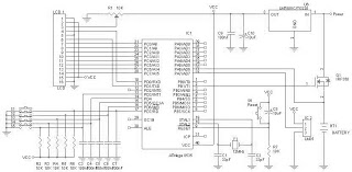
A battery charger can be understood as a device designed to replenish the charge in a battery. An effective charger circuit should provide the necessary resources for efficient and safe battery charging. The AVR-Based Battery Charger utilizes the ATMega...
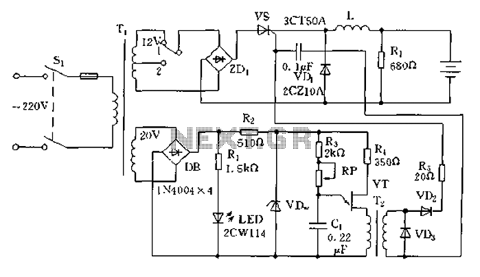
The circuit operates on the principle of a transformer, bridge rectifier, and conditioning for battery charging. The charging current can be adjusted to approximately 12V at 100A. For battery charging, a charging rate of 10 hours requires a charging...
This project involves a mini USB car charger circuit that is simple to construct using only three components. The core of the circuit is the LM78M05 integrated circuit (IC), which is a 5V positive voltage regulator. This IC includes...
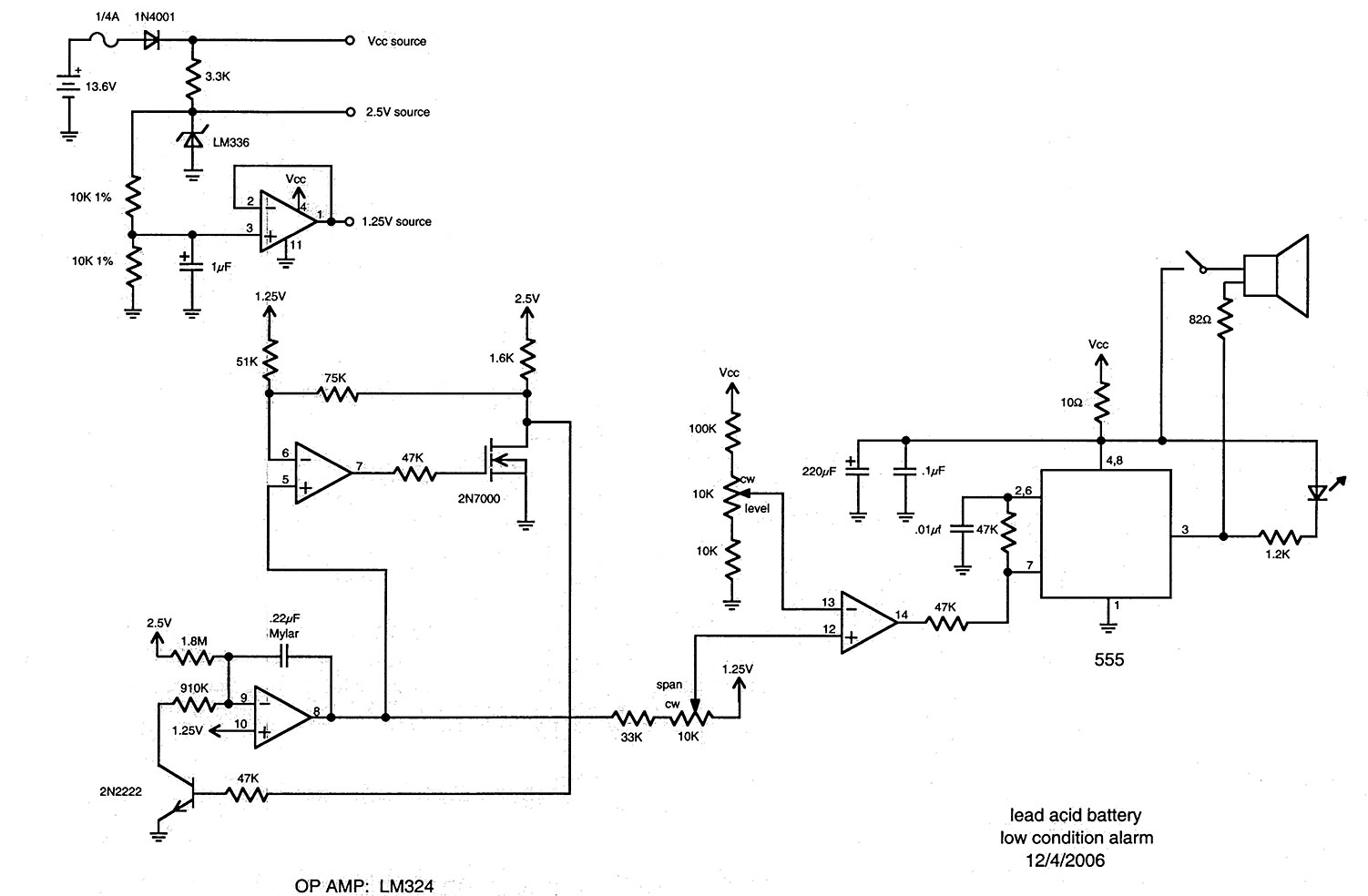
The following circuit is adapted from battery monitors and testers published in The Smith-Kettlewell Technical File (SKTF). The first appearance of this system was "The Smith-Kettlewell Battery Tester, Where Silence is Golden," SKTF, Volume 11, No. 1, Winter 1990....
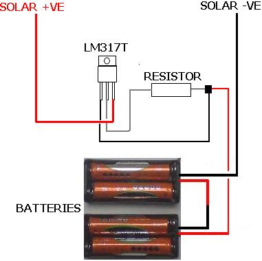
The following circuit illustrates the LM317T IC designed for a solar battery charger circuit diagram. Features include a simple circuit suitable for AA and AAA rechargeable batteries. The LM317T is a versatile linear voltage regulator that can be used in...
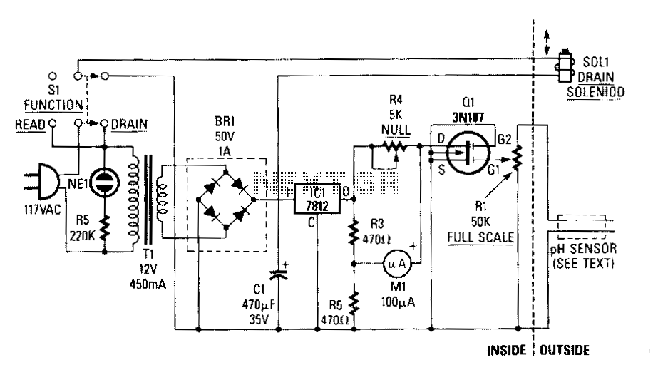
A simple bridge rectifier and a 12-V regulator power the MOSFET sensing circuit. The unregulated output of the bridge rectifier operates the drain solenoid via switch S1. The sensor itself is built from two electrodes: one made of copper...