A LOW-BATTERY ALARM FOR 13.6 VOLT LEAD-ACID BATTERIES
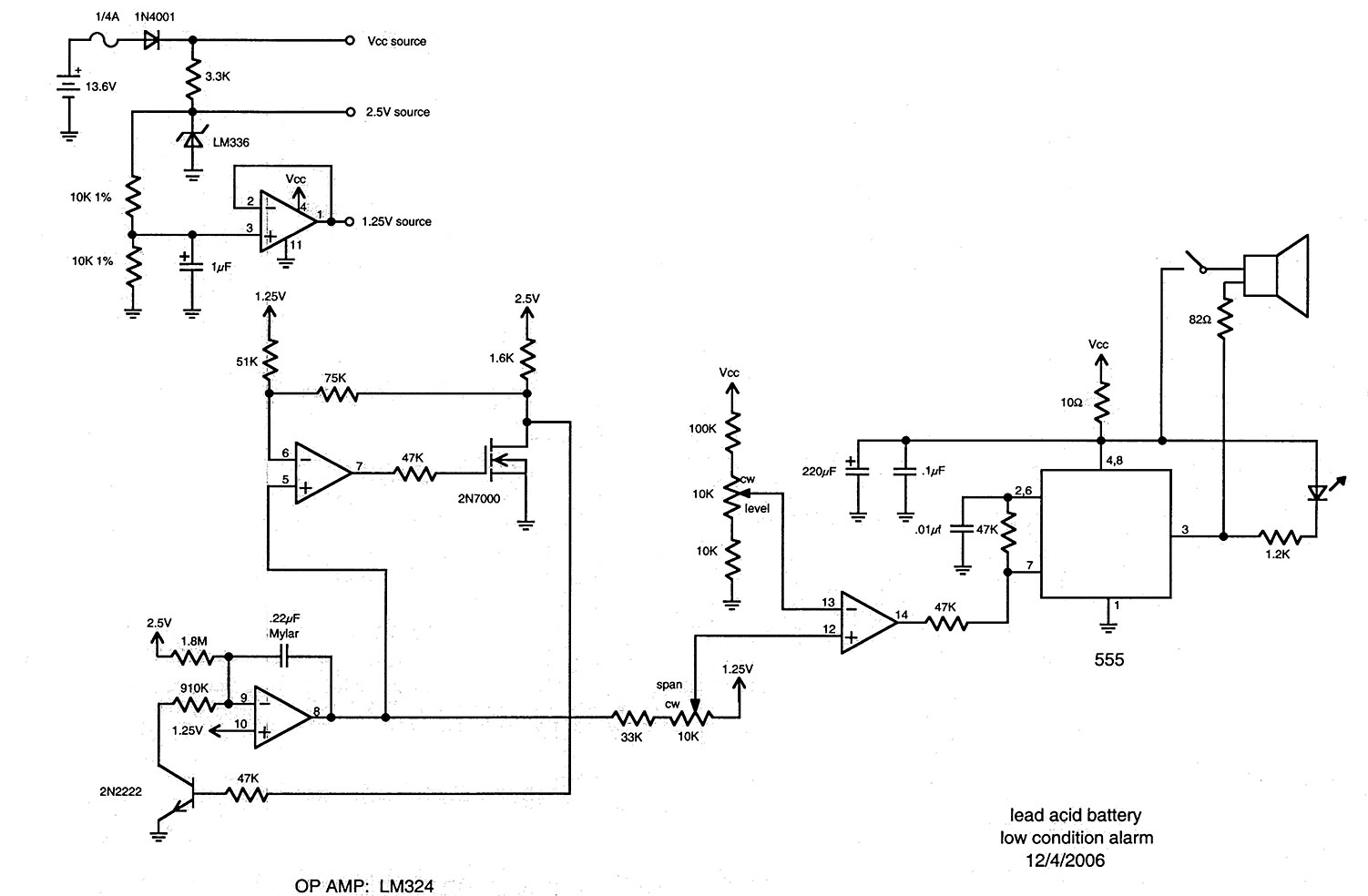
The following circuit is adapted from battery monitors and testers published in The Smith-Kettlewell Technical File (SKTF). The first appearance of this system was "The Smith-Kettlewell Battery Tester, Where Silence is Golden," SKTF, Volume 11, No. 1, Winter 1990. The application here was inspired by a request from a visually impaired ham-radio operator whose transceiver specifically requires that its supply voltage be above 12 volts under load. When powered by a storage battery (as in emergency operation), his unit would malfunction on transmit, which could not be detected by the operator. Thus, he suggested that a sensitive warning system be devised (other than a multi-digit meter) by which the operator would be alerted to an impending low battery condition. Since the time of that request, interest has grown in providing an alarm for riders of motorized wheelchairs—an audible indicator that would warn the user to charge the battery before deep discharge damages it. The values and adjustments shown here are for voltages below 11.66 volts. Smith-Kettlewell's Rehabilitation Engineering Research Center, funded by the National Institute on Disability and Rehabilitation Research, devised a battery-checking scheme that has been integrated into several designs, including a vibratory hearing-aid button-cell tester for the deaf-blind, an auditory adaptation of the Radio Shack Handy Checker, and a test instrument for servicing talking book players. The principle of the readout is to generate bursts (audio beeps or vibratory buzzes for those who cannot hear audio signals); their duration indicates battery voltage. Specifically, an exhausted battery elicits a steady signal, while a fresh battery causes the instrument to fall silent. A "window" (a range of voltages) can be set so that short beeps occur at the top of the range, with beeps becoming longer as the voltage drops, merging into a constant tone at the lowest voltage in this selected range. To accomplish this, the battery voltage is compared with a slow-running triangle wave whose minimum and maximum excursions fall within a desired range; this range is the "window" of battery voltages for which the device is to alert the user. Within this range, the comparator will gate the audio oscillator on and off. Thus, when the battery voltage drops below the positive excursions of the triangle, beeps will be produced. These tone bursts will become longer as the battery voltage drops, allowing more of the triangle wave to enable the oscillator. The instrument is calibrated so that the lowest excursions of the triangle wave coincide with complete exhaustion of the battery. This circuit can be powered from the battery under test, and no on/off switch is necessary. The circuit ground for this auditory device connects to the negative side of the storage battery. The positive of the battery passes through a 1/4-amp fuse to the anode of a protection diode (such as a 1N4001); the cathode of this diode connects to the VCC line of the project. An LM336 2.5V standard has its anode grounded, while its cathode connects through a 3.3K resistor to the VCC line. The junction of the 2.2K and the LM336 forms the 2.5V point, which is routed through two 10K 1% resistors in series to ground. The junction of these resistors is bypassed by a 1uF capacitor (with the negative terminal at ground). This junction is referred to as the "unbuffered 1.25V point." An LM324 quad op-amp has pin 4 connected to the VCC line and pin 11 grounded. Pin 3 of the LM324 is connected to the unbuffered 1.25V point. Pins 1 and 2 are tied together, making pin 1 a buffered 1.25V point. Pin 10 of the LM324 connects to the unbuffered 1.25V point.
The circuit utilizes a comparator to assess the battery voltage against a triangle wave generated by an oscillator. As the battery voltage decreases, the comparator activates the audio oscillator, generating a series of beeps that vary in duration based on the voltage level. This design ensures that users are alerted to low battery conditions before the voltage drops to a critical level, thereby preventing deep discharge and potential damage to the battery.
The choice of components, such as the LM336 voltage reference and the LM324 op-amp, allows for stable operation and precise voltage monitoring. The use of a protection diode ensures safe operation and prevents reverse current that could damage the circuit. The integration of a fuse provides an additional layer of safety, protecting the circuit from overcurrent situations.
The audible feedback mechanism is particularly beneficial for users with visual impairments, providing a non-visual method of monitoring battery status. This circuit can be utilized in various applications beyond ham radios and motorized wheelchairs, including any battery-operated devices where voltage monitoring is crucial for reliable performance. The calibration process ensures that the device responds accurately to the specific battery chemistry and characteristics, making it adaptable to different scenarios. Overall, this circuit design exemplifies a thoughtful approach to accessibility and user safety in electronic devices.[The following circuit is adapted from battery monitors and testers published in The Smith-Kettlewell Technical File (SKTF). The first appearance of this system was "The Smith-Kettlewell Battery Tester, Where Silence is Golden", SKTF, Volume 11, No.
1, Winter 1990. ] The application here was inspired by a request from a visually impaired ham-radio operator whose "rig" (transceiver) specifically requires that its supply voltage be above 12 volts under load. When powered by a storage battery (as in emergency operation), his unit would malfunction on transmit, which could not be detected by the operator.
Thus, he suggested that a sensitive warning system be devised (other than a multi-digit meter) by which the operator would be alerted to an impending low battery condition. Since the time of that request, we have become interested in providing an alarm for riders of motorized wheelchairs - an audible indicator that would warn the user that he should put a charge on the battery before "deep discharge" damages it.
Thus, the values and adjustments shown here are for voltages below 11. 66 volts. Smith-Kettlewell`s "Rehabilitation Engineering Research Center", funded by the National Institute on Disability and Rehabilitation Research, devised a battery-checking scheme which has found its way into several of our designs - a vibratory hearing-aid button-cell tester for the deaf-blind, an auditory adaptation of the Radio Shack "Handy Checker" (see the above byline), and a test instrument for servicing "talking book" players. The principle of our readout is to generate bursts (audio "beeps", or vibratory "buzzes" for those who cannot hear audio signals); their duration indicates battery voltage.
(In this implementation, the output is auditory. ) Specifically, an exhausted battery elicits a steady signal; a fresh battery causes the instrument to fall silent. A "window" (a range of voltages) can be set so that short beeps occur at the top of the range, with beeps becoming longer and longer as the voltage drops, joining together to make a constant tone at the lowest voltage in this selected range.
To accomplish this, the battery voltage is "compared" with a slow-running triangle wave whose minimum and maximum excursions fall within a desired range; this range is the "window" of battery voltages for which the device is to alert the user. Within this range, the comparator will gate the audio oscillator on and off. Thus, when the battery voltage drops below the positive excursions of the triangle, beeps will be produced.
Short at first, these tone bursts will become longer and longer as the battery voltage drops, allowing more and more of the triangle wave to enable the oscillator. The instrument is calibrated so that the lowest excursions of the triangle wave coincide with complete exhaustion of the battery.
This circuit can be powered from the battery under test. No on/off switch is necessary. "Circuit ground" (for this auditory device) goes to the negative side of the storage battery. The positive of the battery goes through a 1/4-amp fuse to the anode of a protection diode (such as a 1N4001); the cathode of this diode goes to the "VCC line" of the project. An LM336 2. 5V standard has its "anode" grounded; its "cathode" goes through 3. 3K to the VCC line. The junction of the 2. 2K and the 336 is the 2. 5V point. This 2. 5V point goes through two 10K 1% resistors in series to ground. The junction of these resistors is bypassed by 1uF (negative of this cap at ground). The junction of these 10K 1% resistors is called the "unbuffered 1. 25V point". An Lm324 quad op-amp has pin 4 going to the VCC line; pin 11 is grounded. Pin 3 of the 324 goes to the aforementioned unbuffered 1. 25V point (the junction of the 1% resistors). Pins 1 and 2 are tied together, and thus, pin 1 is a buffered 1. 25V point. Pin 10 of the 324 goes to the unbuffered 1. 25V point (the junction of the 1% resistor 🔗 External reference

