
usb car charger

The mini USB car charger circuit is designed to efficiently convert the higher voltage from a car battery (typically 12V DC) to a lower, safer voltage suitable for USB-powered devices (5V DC). The LM78M05 voltage regulator serves as the primary component, providing a stable output voltage while incorporating essential safety features to protect both the circuit and the connected devices.
The circuit layout typically includes the LM78M05 IC, input and output capacitors, and a connection point for the cigarette lighter socket. The input capacitor, usually a ceramic or electrolytic capacitor, is connected to the input pin of the LM78M05 to filter any high-frequency noise and stabilize the input voltage. The output capacitor, also placed close to the output pin, helps to maintain a steady output voltage under varying load conditions.
The output current rating of 500mA indicates that the circuit can charge devices such as smartphones, tablets, and other USB gadgets efficiently. For applications requiring higher output current, alternative configurations using different voltage regulators or additional components may be employed, such as the mentioned 12V to 9V converter capable of delivering 1000mA.
To ensure the reliability and safety of the circuit, it is crucial to follow proper wiring practices and verify the output voltage with a multimeter before connecting any devices. This precaution helps to avoid potential damage to sensitive electronics due to incorrect voltage levels. Overall, this mini USB car charger circuit represents a practical solution for charging USB devices on the go, leveraging the car's battery power efficiently.This is a project of a mini USB car charger circuit. The circuit is very simple to build using only three components. Heart of the circuit is a LM78M05 IC which is a 5V positive voltage regulator IC. This IC has many built in featuers like thermal overload protection, short circuit protection, safe operating area protection etc. The circuit can b e easily connected with the cigar socket in car and convert 12 volt DC to 5 volt DC and charge many USB devices. Out put current of the circuit is 500mA which is enough to charge any USB device. The circuit is basically a DC to DC converter and can also be used to run many 5 to 6 volt DC device from car battery.
There are also other similar circuits which you can use to run any 5V or 9V devices from car battery like 12V to 5V converter and 12V to 9V converter with 1000mA output current. Note: It is adviced to check and confirm the connections and 5 volt output voltage of the circuit with multimeter before connecting any USB device for charging to make sure the circuit is working fine without any soldering or wiring error and providing 5 volt DC output.
🔗 External reference
Related Circuits
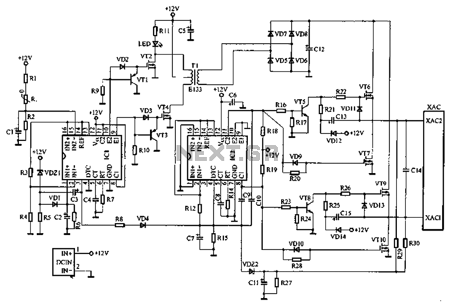
Car inverter specifications include an input voltage range of DC 10V to 14.5V, output voltage of AC 200V to 220V with a tolerance of 10%, output frequency of 50Hz with a tolerance of 5%, and an output power range...
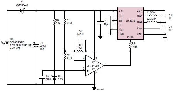
A simple supercapacitor charger electronic project can be designed using the LTC3625 integrated circuit (IC) from Linear Technology. This circuit is capable of charging two supercapacitors in series to a fixed output voltage of either 4.8V/5.3V or 4V/4.5V, which...
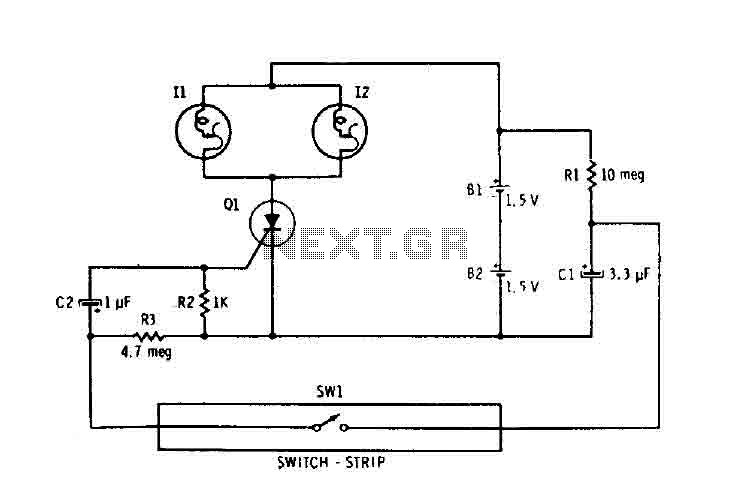
Capacitor C1 is connected continuously through a supply of 3 volts to a 10 megohm resistor R1. The capacitor charges relatively slowly to 3 volts. When switch SW1 is closed, it connects the charged capacitor C1 in series with...
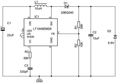
The phone is a Siemens S65. The official charger that came with the phone specifies an output of 5V at 420mA. However, actual performance may vary from the printed specifications. Voltage measurements indicated that without the phone connected, the...
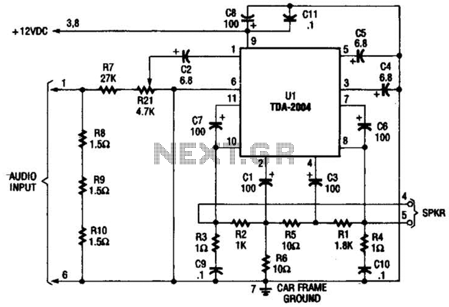
Only one channel of this circuit is shown. The other is practically identical. The input to the circuit, taken from the speaker output of a car radio, is divided into two paths. In one path, a high-power divider network...
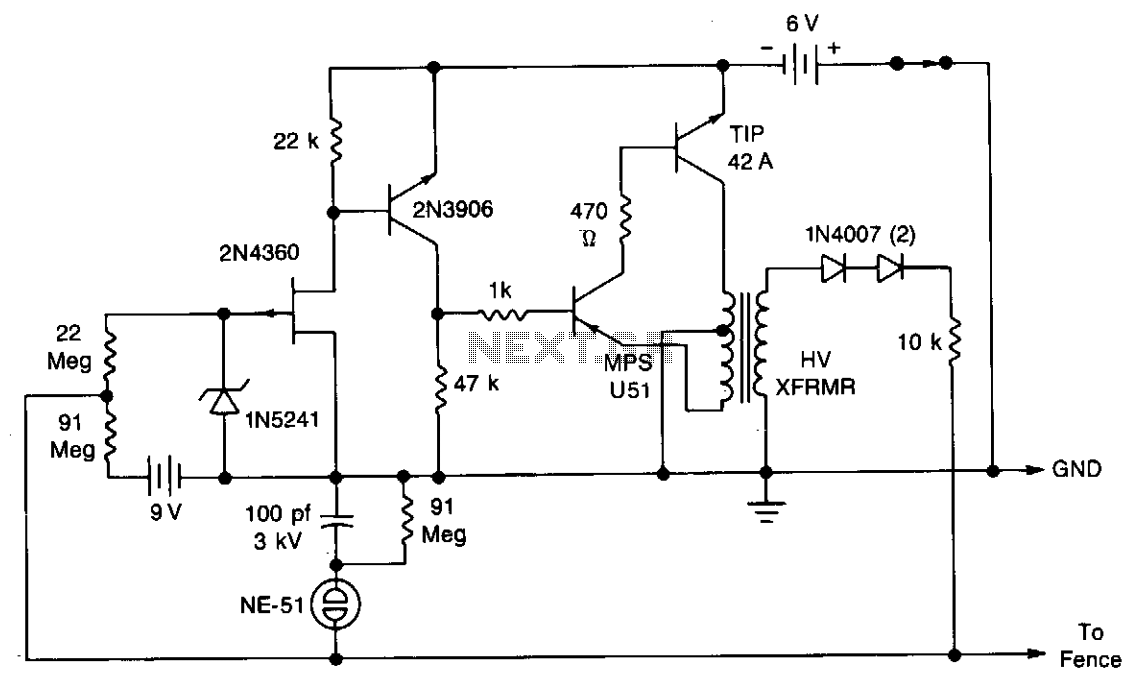
A touch-sensing circuit maintains the high-voltage generator in an off state until contact is made with the fence wire. When something touches the fence sensing circuit wire, it activates the high-voltage generator, which delivers a series of 500-microsecond pulses...