
120VAC 10Amp DPDT Relay question aquarium design dpdt relay

The aquarium design incorporates a DPDT (Double Pole Double Throw) relay, which is essential for controlling multiple circuits within the system. This relay can handle a load of up to 400 watts, making it suitable for various applications, including powering lights, pumps, or filtration systems in the aquarium setup. The relay's configuration allows for the switching of two different circuits or devices simultaneously, providing flexibility in controlling the aquarium's electrical components.
The 12V inverter is a critical component that converts DC power from the battery to AC power, allowing for the operation of standard AC devices. The inverter's efficiency is enhanced by the low power consumption of the associated components, including the 12V DC relay, transformer, and diodes. These components work together to ensure that the system operates smoothly without drawing excessive power, which is particularly beneficial in battery-operated systems where energy conservation is paramount.
The trickle charging mechanism for the battery is an important aspect of maintaining battery health and ensuring a consistent power supply. This method of charging allows for the gradual replenishment of the battery's charge, which is vital for long-term operation. However, further clarification is needed regarding the specific method employed for trickle charging, as well as the operational status of the battery within the system.
Overall, this aquarium design effectively integrates a DPDT relay and a 12V inverter to manage power distribution while maintaining efficiency and reliability in its operation.aquarium design, dpdt relay, 12v inverter: ONE: The relay you have selected is rated plenty sufficient for a 400 watt load. TWO: The 12v dc relay, transformer and diodes are using very little power so efficiency is of little concern.
THREE: How are you tickle charging the battery? Is it running.. 🔗 External reference
Related Circuits
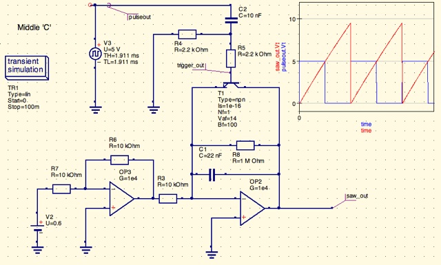
A design for a digitally controlled analog oscillator is being developed. The control voltage is generated by a microcontroller (Arduino) and is utilized through two operational amplifiers, along with a resistor and capacitor network that forms an integrator circuit....
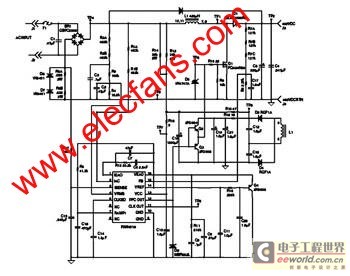
The FAN4810 operates as a continuous conduction mode (CCM) power factor correction (PFC) controller. It features an internal safety detection mechanism that prevents circuit malfunction due to component damage. The device has a power-handling capability of up to 1A,...
To troubleshoot the headlight system, switch the headlight switch ON and OFF and check if the headlight relay can be felt and heard clicking. This is indicated in the first schematic on the left side of the diagram. The...

The right leg driver circuit is where many amplifier board circuits' common signals are summed and inverted through the Right Leg Driver circuit and sent back to the body to cancel out common voltages. This ground point could be...
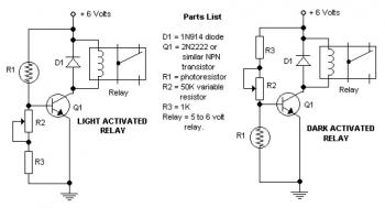
The potentiometer adjusts the trigger level. The diode in the circuit diagram is specified as 1N914, which is suitable for light-duty relays; however, since the 1N914 is a signal diode, it is not ideal for this application. A 1N4001...
The widespread application of Flash technology in microprocessors has led to significant advancements in the development and utilization of one-chip computers. Designers have transitioned from traditional in-circuit emulators (ICE) and JTAG interfaces to more cost-effective and user-friendly development methods....