
120vac lamp chaser circuit

This circuit utilizes a 4017 decade counter to create a sequential lighting effect across multiple channels. The primary function of the 4017 is to count pulses and activate the corresponding output pins in a sequential manner. Each output pin can control a solid-state relay, which in turn controls the AC lamps. The relays are crucial for managing the higher voltage and current required by the AC lamps, while the 4017 counter operates at lower voltages suitable for logic circuits.
The circuit's design includes a timing mechanism, typically implemented using a 555 timer or similar oscillator circuit, generating a clock signal that drives the 4017. The clock frequency can be adjusted to change the speed of the LED chaser effect. The 360-ohm resistor plays a vital role in protecting the LED within the relay by limiting the current, ensuring that it operates within safe parameters.
In terms of expansion, the circuit can accommodate additional channels by integrating more relays and driver transistors. This scalability allows for a customizable number of outputs, depending on the user's requirements. The reset functionality of the 4017, connected to an output pin, enables the user to define the sequence length, allowing for flexible configurations of the lighting pattern.
For practical applications, this circuit can be utilized in various environments such as decorative lighting displays, stage lighting, or any scenario where sequential lighting effects are desired. The use of solid-state relays enhances the reliability and longevity of the circuit, as they do not have mechanical components that can wear out over time. Overall, this circuit design offers an efficient and effective solution for controlling multiple AC lamps in a sequenced manner.This circuit is design for same as the 10 channel LED sequencer with the addition of solid state relays to control the AC lamps. This circuit is control using relays. This is the figure of the circuit. The relay shown in the diagram is a Radio Shack 3 amp unit (part no. 275-310) that requires 1. 2 volts DC to activate. No current spec was given but I assume it needs just a few milliamps to light the internal LED. A 360 ohm resistor is shown which would limit the current to 17 mA using a 9 volt supply. I tested the circuit using a solid state relay (of unknown type) which required only 1. 5 mA at 3 volts but operates up to 30 volts DC and a much higher current. The chaser circuit can be expanded up to 10 channels with additional relays and driver transistors. The 4017 decade counter reset line (pin 15) is connected to the fifth count (pin 10) so that the lamps sequence from 1 to 4 and then repeat. For additional stages the reset pin would be connected to a higher count. 🔗 External reference
Related Circuits
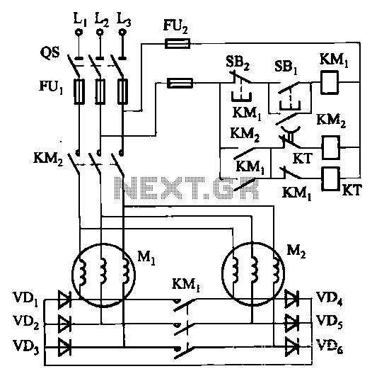
The circuit depicted in Figure 3-157 is designed for motors with a capacity of no more than 11 kW, requiring precise stopping capabilities. Upon shutdown, contact KMi releases, and the motor stator windings are configured into a three-phase rectifier...
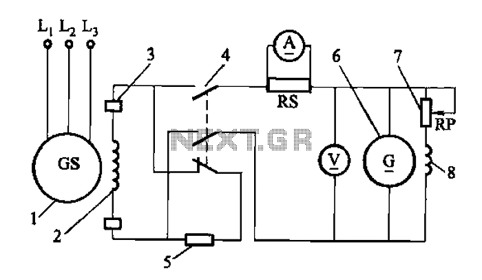
Adjust the exciter field rheostat RP to change the exciter output voltage, which in turn adjusts the generator excitation current, allowing for modifications to the generator output voltage for various purposes. The exciter field rheostat (RP) is a critical...
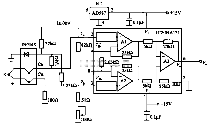
The AD587 is a precision voltage reference providing a 10 V output, generated using a 27 kΩ resistor along with a compensation diode (1N4148) and a thermocouple. This setup connects to the VI + N terminal of a differential...
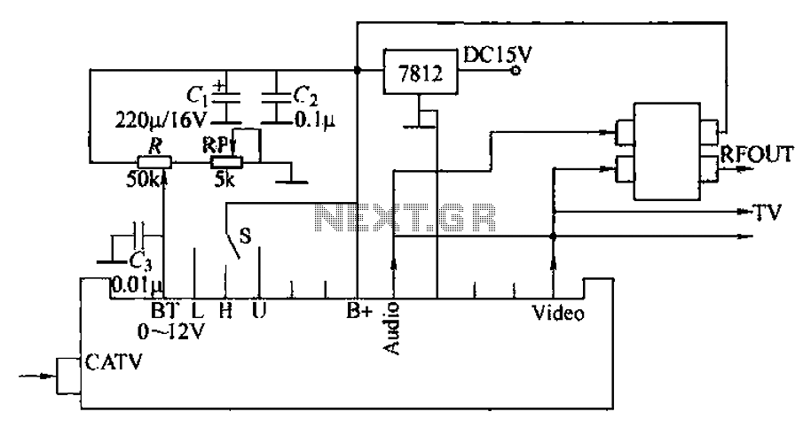
The circuit utilizes two main components: an integrated electronic tuner with AV output, commonly referred to as the tuner, which can receive CATV full channel TV signals and output a video signal (Vttko) along with an audio signal (Audio)....

The circuit is built around a single 4093 quad 2-input NAND Schmitt trigger. Two gates from that quad package (U1-a and U1-b) are configured as a set-reset flip-flop. The 4093 integrated circuit (IC) contains four independent 2-input NAND gates with...
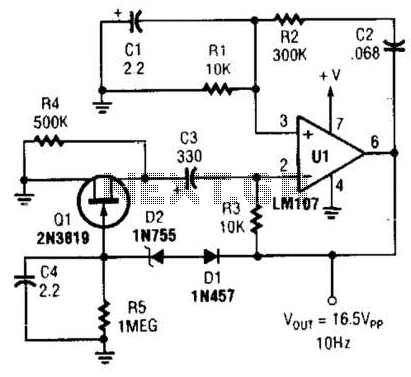
This Wien-bridge sine-wave oscillator utilizes a 2N3819 as an amplitude stabilizer. The 2N3819 functions as a variable-resistance element within the Wien bridge. The Wien-bridge oscillator is a type of electronic oscillator that generates sine waves. It employs a bridge circuit...