
DC exciter excitation mode circuit

The exciter field rheostat (RP) is a critical component in the control of generator output voltage. By adjusting this rheostat, the resistance in the exciter circuit can be varied, which directly influences the voltage produced by the exciter. This change in exciter output voltage modifies the excitation current supplied to the generator's rotor, which is essential for maintaining stable voltage levels under varying load conditions.
In a typical setup, the exciter field rheostat is connected in series with the exciter field winding. When the rheostat is adjusted to a higher resistance, the current through the exciter winding decreases, leading to a lower magnetic field strength in the rotor. Consequently, this results in a decrease in the voltage output of the generator. Conversely, reducing the resistance of the rheostat increases the exciter output voltage, enhancing the excitation current and thereby increasing the generator's output voltage.
For effective operation, the exciter field rheostat should be calibrated correctly to ensure that the generator can respond adequately to load changes. It is important to monitor the excitation current and generator output voltage regularly to ensure that they remain within specified limits, preventing potential damage to the generator and connected systems. Additionally, the rheostat should be selected based on the rated capacity of the generator and the expected variations in load to ensure optimal performance and reliability. Proper maintenance and periodic testing of the rheostat's functionality are also essential to ensure long-term operational effectiveness.Adjust the exciter field rheostat RP, can change the exciter output voltage to adjust the generator excitation current section to achieve the change the generator output voltag e purposes.
Related Circuits
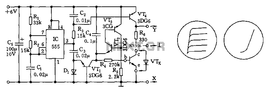
The transistor characteristic curve tracer circuit depicted in Figure 555 illustrates the characteristics of a transistor. It utilizes two voltages: a step wave applied to the base (b) to generate different base currents (Ib), and a sawtooth waveform at...
This electronic organ circuit is straightforward to construct and primarily consists of an emitter-coupled oscillator formed by transistors T2 and T3. A square wave voltage can be obtained from the collector of T3 (X2), which imparts a clarinet-like quality...
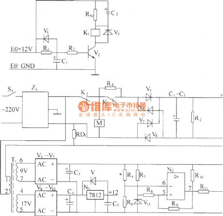
220V (50Hz) alternating voltage passes through the Z1 circuit filter, which filters the signal before sending it to the connection point of the AC overvoltage and undervoltage protection relay K2. During normal operation, the K2 connection point should be...
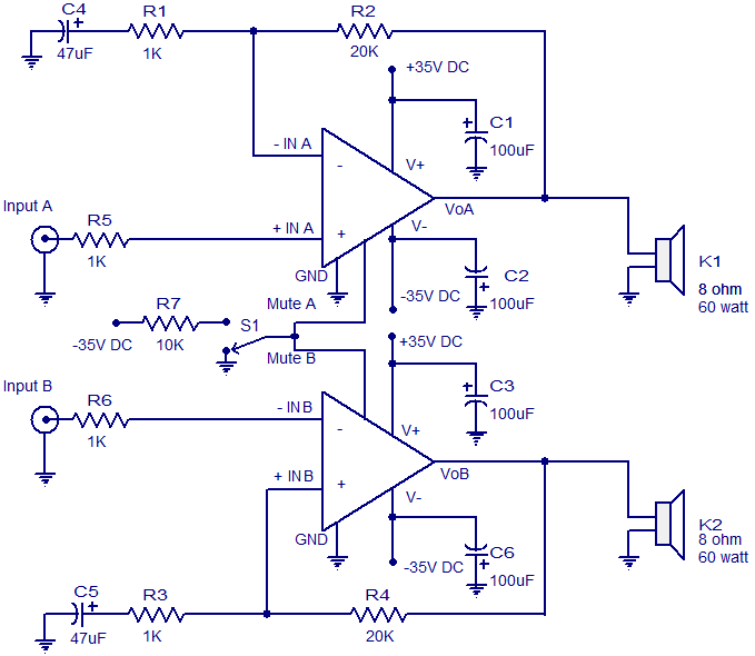
The circuit diagram presented is for a 2 x 60 Watt stereo amplifier utilizing the LM4780 from National Semiconductors. The LM4780 is an excellent audio amplifier integrated circuit capable of delivering 60W RMS power output per channel into 8-ohm...
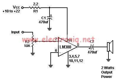
A simple audio amplifier can be designed using the LM380 along with a few external components. This amplifier features a wide supply voltage range, an input impedance of 150 kΩ, low distortion, and a current capability of 1.3 A. The...
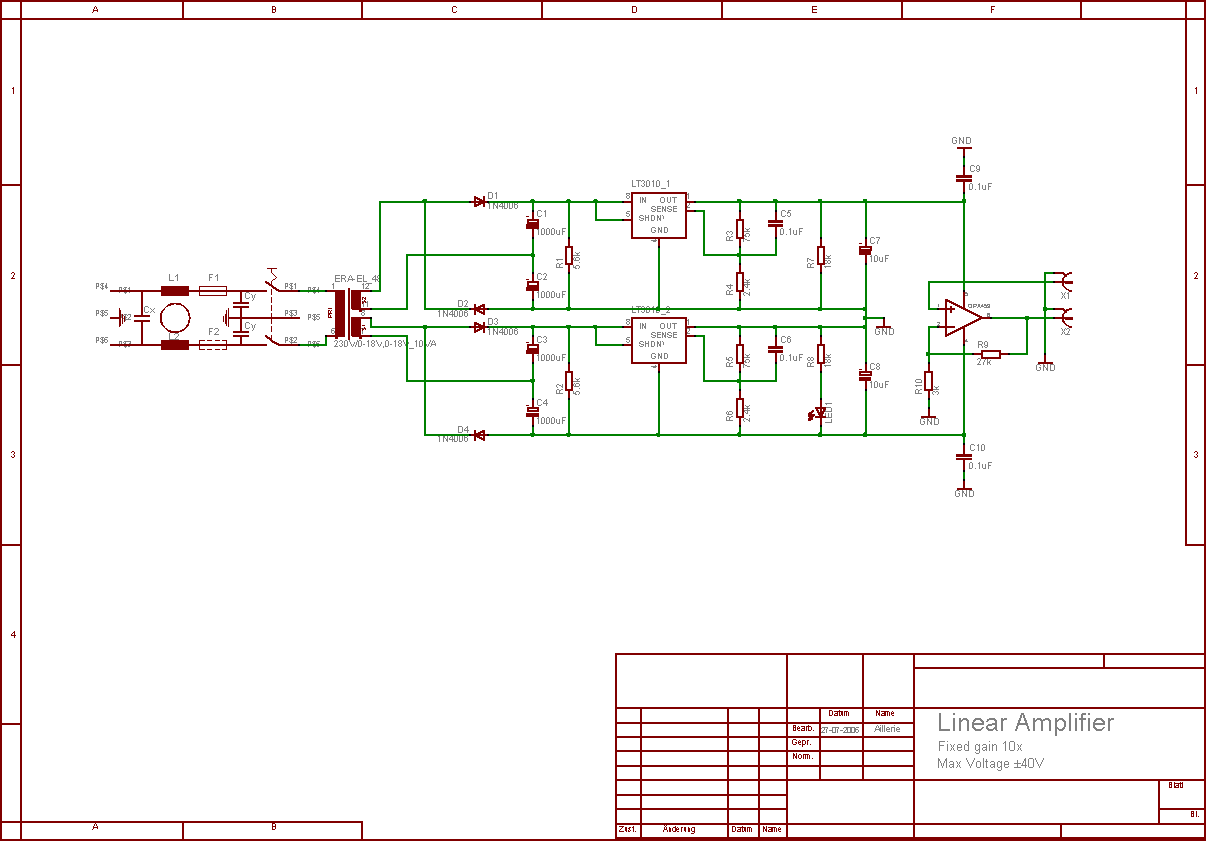
The aim of this project was to develop a linear analogue amplifier designed for laboratory use. This amplifier has to realise a voltage amplification of 10x and is intended to amplify function generator signals for tests. Power supply requirements:...