
120VAC Lamp Chaser circuit
The circuit operates by utilizing the solid-state relay to switch AC lamps on and off in synchronization with a sequence determined by the LED indicators. The relay's low activation voltage (1.2 volts DC) makes it suitable for integration with various low-voltage control circuits, ensuring compatibility with microcontrollers or other logic devices that can output this voltage level.
When designing the circuit, the 360-ohm resistor plays a critical role in limiting the current flowing through the relay's activation circuit. Given a 9-volt supply, Ohm's law (V = IR) dictates that the maximum current through the resistor can be calculated as follows:
I = V/R = 9V / 360Ω ≈ 0.025A or 25mA.
This current is well within the operational limits for most low-power control applications. However, it is essential to confirm that the relay's internal LED can operate effectively with this current level, ensuring reliable performance without risk of damage.
The solid-state relay itself is designed to handle up to 3 amps of AC current, making it suitable for controlling standard household lamps or other light fixtures. The use of solid-state components provides advantages over traditional electromechanical relays, including faster switching times, longer operational life, and reduced electromagnetic interference.
In summary, this circuit effectively combines the functionality of an LED sequencer with the robust capabilities of solid-state relays, providing a reliable method for controlling AC lamps in a sequenced manner. Careful consideration should be given to component ratings and specifications to ensure optimal performance and safety in the final application.This circuit is basically the same as the channel LED sequencer with the addition of solid state relays to control the AC lamps. The relay shown in the diagram is a Radio Shack 3 amp unit (part no. 275-310) that requires 1.2 volts DC to activate. No current spec was given but I assume it needs just a few milliamps to light the internal LED. A 360 ohm resistor is shown which would limit the current to 17 mA using a 9 volt supply.. 🔗 External reference
Related Circuits
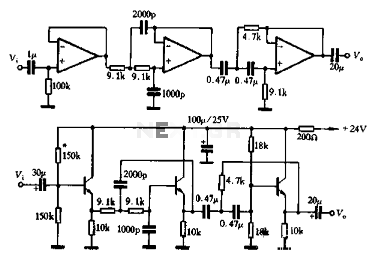
A band-pass filter is presented as a single-channel circuit diagram in this article, specifically for audio applications. The filter has a high cutoff frequency (fH) of 50 Hz and a low cutoff frequency (fL) of 13 kHz, as illustrated...
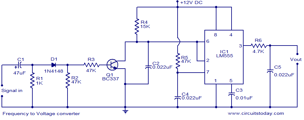
A simple frequency to voltage (F to V) converter circuit utilizing the LM555 Timer IC. This circuit has numerous applications in digital frequency meters, tachometers, and other related devices. The frequency to voltage (F to V) converter is a crucial...
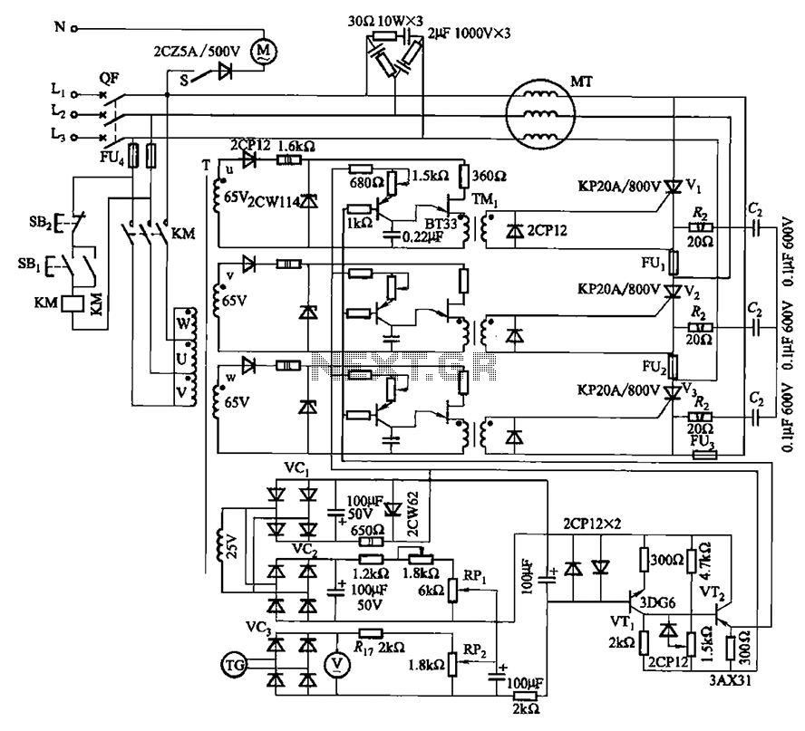
The circuit depicted in Figure 3-181 comprises three thyristors, labeled V1 to V3. The trigger circuit utilizes a single-junction transistor relaxation oscillator. The speed control circuit incorporates negative feedback. A master adjust potentiometer, designated as RPi, is used to...
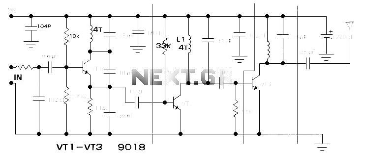
The components available were utilized to create a long-range FM radio transmitter operating within the 88-108 MHz band, designed for playing music. The circuit includes a power section that rectifies mains voltage to provide a stable 12V DC for...
C1 is a 1000 microfarad aluminum electrolytic capacitor. For loads less than 100mA, a 220 microfarad capacitor can be substituted. The voltage rating should be 2.5 times the output voltage. C1 serves as a critical component in various electronic circuits,...
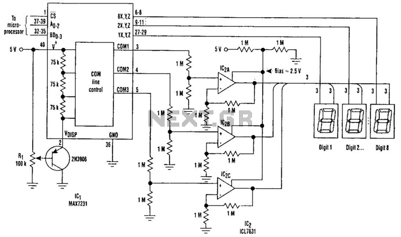
Large LCD devices with one or more displays exhibit significant driving capacitance to the driver circuits. To address this issue, the drive circuit incorporates a buffer amplifier for each of the three common lines. Each amplifier can be programmed...