
123 Game - All MCU-free

When the player touches the right-hand contact with R4, only LED D3 lights up. If the left-hand contact is touched with R3, LEDs D1 and D2 illuminate. Touching the middle contact activates diodes D4 and D5, causing all three LEDs to light up. The two diodes prevent all three LEDs from lighting when the player touches either the left-hand or right-hand contact. The key to the game lies in the assignment of the 30 sockets to three types of logic, representing three ideal next moves. Working backward from the goal, no further moves are possible once the goal is reached, leading to the last socket not being connected to anything. The socket just before the goal is connected to R4, as the computer aims to be exactly one step ahead. The socket two steps before the goal is connected to R3, as it wants to move two steps. Three moves before the finish, a three-step move is optimal for an immediate victory, connecting this socket to D4/D5. The correct response of the computer is indicated by numbers next to each position in the schematic. As the two opponents take turns, the electronics consistently strives to reach strategically favorable positions, marked by arrows. If the electronics reaches one of these positions, it becomes impossible for the human player to win, meaning the human can only secure a victory by starting first and always making the correct move.
The circuit operates on the principles of logic gates created using diodes, which allows for the determination of the optimal move based on the current position of the game token. Each of the 30 sockets corresponds to a specific position on the game path, and the arrangement ensures that the game progresses in a serpentine manner, facilitating a straightforward interaction between the player and the machine. The design emphasizes minimalism and efficiency, eliminating the need for complex microcontroller programming while still providing a challenging and engaging gameplay experience.
The diodes used in the circuit serve multiple purposes, including preventing incorrect LED indications and ensuring that only the appropriate responses are activated based on the player's input. The arrangement of the sockets and the logic behind the connections create a dynamic interaction where the machine anticipates the player's moves, thus enhancing the strategic depth of the game. The schematic can be further analyzed to understand the specific diode configurations and their interactions, which contribute to the overall functionality of the game. This design exemplifies the effectiveness of simple electronic components in creating an engaging and competitive game environment.This electronic game pits a human player against the ‘machine’. The opponents use a common ‘game token’ and take turns moving along a path by one, two or three steps, and the winner is the first one to reach the goal exactly. Incredibly enough, this simple version of the ‘123’ game can be built without a microcontroller, and it’s almost impossible to beat.
The electronics for this is built using only diode logic (Figure 1). The ‘ input inter face’ consists essentially of 30 miniature sockets to which a probe tip can be connected to mark the position of the ‘game token’. To make the game more compact, the sockets are arranged in a grid so the route along the sockets follows a serpentine path (Figure 2).
The starting position is at the bottom right, and the goal is in the middle of the playing area. The electronics becomes the ‘active player’ when the button is pressed. The player touches the right-hand contact with R4 (only LED D3 lights up), the left-hand contact with R3 (LEDs D1 and D2 light up), or the middle contact with diodes D4 and D5 (all three LEDs light up). The two diodes prevent all three LEDs from lighting up if the player touches the left-hand or right-hand contact.
The key to all this lies in the assignment of the 30 sockets to the three types of logic, which means the three types of ideal next move. Working backward from the goal, no further move is possible when the goal is reached. For this reason, the last socket is not connected to anything. At the socket just before the goal, the ‘computer’ naturally wants to be exactly one step in front. Consequently, this socket is connected to R4. At the second socket before the goal, the electronics wants to move by two steps. This socket is thus connected to R3. Obviously, three moves before the finish, a three-step is best as it leads to instant victory. Consequently this socket is connected to D4/D5. The correct response of the ‘computer’ is shown in Figure 2 by the number next to each position. As the two opponents take turns playing, the electronics always tries to arrive at a strategically favourable position (marked by the arrows).
If the electronics manages to reach one of these positions, it’s impossible for the human player to win. This means that the human player can only win by starting first and always making the right move. 🔗 External reference
Related Circuits
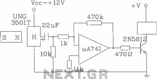
The UGN-3501T Hall sensor features a highly sensitive counter circuit diagram, allowing it to detect very small changes in magnetic fields. This capability enables the detection of ferrous metals. Utilizing this characteristic, it can be employed to count loads....
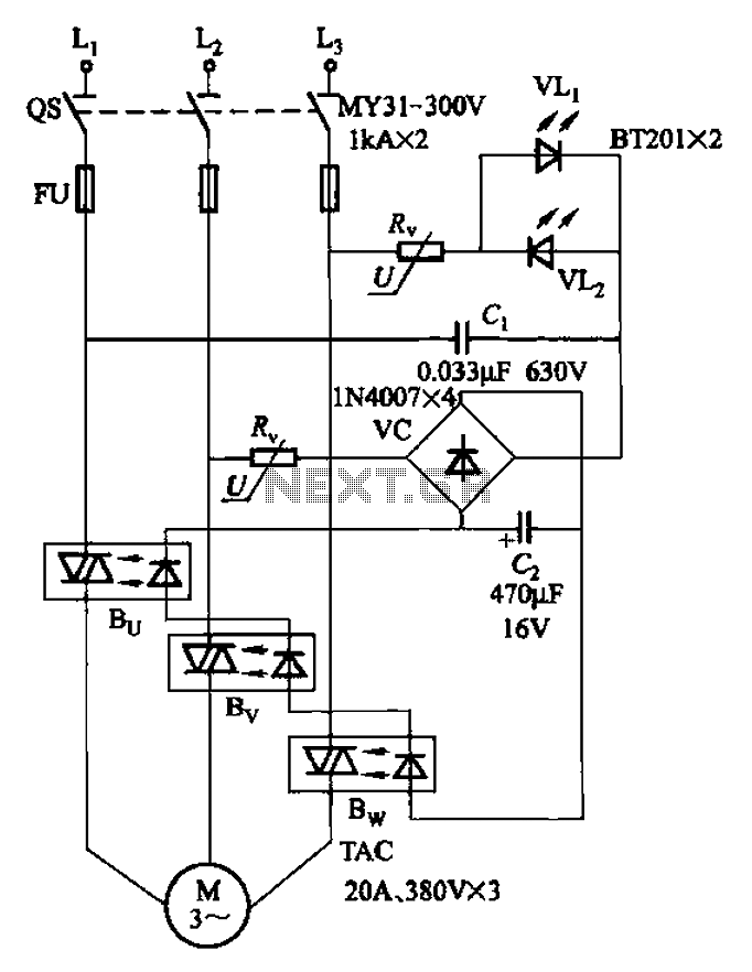
The circuit depicted in Figure 3-93 is integrated with an optical phase sequence protection relay. The circuit in question is designed to provide phase sequence protection using an optical relay mechanism. Optical phase sequence protection relays are crucial in applications...

One of the key challenges in the design of 4- to 20-mA current transmitters is the voltage-to-current conversion stage. Conventional transmitters use multiple op amps and transistors to perform the conversion function. These approaches have been around for a...

The count switching circuit consists of an electronic switch and a pulse delay circuit for control. The count switching circuit is designed to manage the switching of signals in a controlled manner. The electronic switch serves as the primary component...

The A1301 and A1302 are continuous-time, ratiometric, linear Hall-effect sensor integrated circuits (ICs). These sensors are designed to provide an accurate voltage output that is proportional to the magnetic field applied. The quiescent output voltage of these devices is...
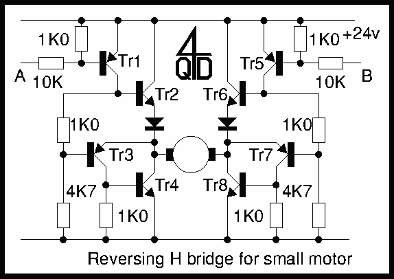
Two inputs, A and B, control the bridge. With both high (or open circuit) both ends of the motor are connected to 0v. Connect A low and Tr2 turns on causing the motor to go forward. Connect B low...