
H bridge switch for small motors

The described circuit functions as a H-bridge motor driver, which allows for the control of a DC motor's direction and operation based on two input signals, A and B. The H-bridge configuration consists of four transistors (Tr1, Tr2, Tr3, Tr4) arranged in such a way that enables the motor to be powered in either direction or to be turned off entirely.
When both inputs A and B are in a high state (or open circuit), the transistors are configured to connect both terminals of the motor to ground (0V), effectively preventing any voltage from being applied across the motor. This state is often referred to as the "brake" state, where the motor is held stationary.
To drive the motor forward, input A is set to low (0V). This action turns on transistor Tr2, which allows current to flow from the power supply through the motor and back to ground via Tr2. The other transistors (Tr1, Tr3, Tr4) remain off, ensuring that the current flows in the correct direction to drive the motor forward.
Conversely, to reverse the motor's direction, input B is set to low. This activates transistor Tr6, which enables current to flow in the opposite direction through the motor. In this case, Tr2 remains off, and the current flows from the power supply through the motor and back to ground via Tr6, thus reversing the motor's rotation.
If both inputs A and B are set to low, both ends of the motor become connected to the high state (supply voltage), resulting in no potential difference across the motor terminals. Consequently, the motor is turned off, effectively stopping any motion.
This H-bridge design allows for precise control of the motor's operation, making it suitable for various applications, including robotics, automation, and motor control systems. Proper selection of transistors capable of handling the motor's current and voltage ratings is crucial for reliable operation, and additional components such as diodes may be included to protect against back EMF generated by the motor during operation.Two inputs, A and B, control the bridge. With both high (or open circuit) both ends of the motor are connected to 0v. Connect A low and Tr2 turns on causing the motor to go forward. Connect B low and Tr6 turns on, reversing the motor. If A and B are both low, both ends of the motor are high, so the motor is off. 🔗 External reference
Related Circuits
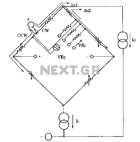
The circuit for zero and span adjustment consists of a feedback resistor network and a differential pressure sensing bridge measuring circuit. A constant current source, IO, represents the output current. The resistances of the four bridge arms are R1S,...
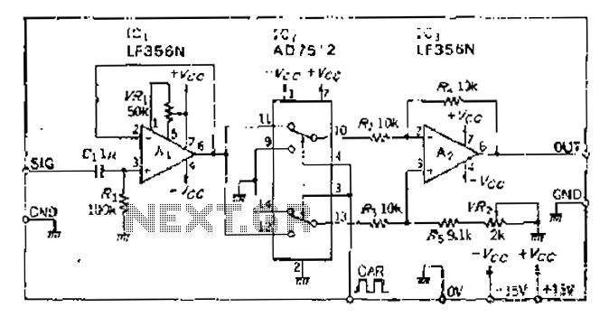
An analog switch (double loop, double-break) and a differential modulation amplifier are used in this circuit. The carrier control switch operates by switching contacts at specific times, inverting the input modulation wave. When the next carrier signal is applied...
This temperature switch utilizes several discrete components to activate a buzzer when the ambient temperature rises. It is suitable for use as a straightforward fire alarm indicator. The temperature switch circuit is designed to monitor environmental temperature changes and provide...
H-Bridge This circuit drives small DC motors up to about 100 watts or 5 amps or 40 volts, whichever comes first. Using bigger parts could make it more powerful. Using a real H-bridge IC makes sense for this size of...
The ability to turn electrical devices ON or OFF using a remote control is a well-established concept, with numerous devices effectively performing this function. To implement a remote control system for switching electrical devices, a typical schematic would include several...
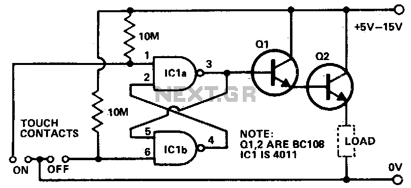
Touching the on contacts with a finger brings pin 3 high, turning on the Darlington pair and supplying power to the load (transistor radio, etc.). Q1 must be a high-gain transistor, and Q2 is chosen for the current required...