
125 Motorcycle electronic ignition circuit diagram

An AC magneto ignition system is employed to generate electrical energy for igniting the engine. This system begins with the AC magneto producing alternating current (AC), which is then rectified by diode D1. The rectified voltage is stored in capacitor C1, which acts as a reservoir of energy for the circuit. Further rectification occurs through diode D4, while resistors R9 and capacitors C7 and C8 serve to filter the rectified output, smoothing the voltage supplied to the integrated circuit (IC).
The operation of the ignition system is controlled by switch SW; when this switch is grounded, the electronic ignition is disabled, preventing any firing of the spark plug. The circuit is designed to make contact with the ignition coil, allowing a trigger voltage to flow through transistors BG1 and BG2. This voltage is fed into the integrated circuit at input pins 2 and 7, which processes the signal and generates a trigger output at pin 10.
The resistors R1 and R2 create a voltage divider that applies a controlled voltage to the gate of the silicon-controlled rectifier (SCR). Once the SCR receives this signal, it begins conduction, allowing capacitor C1 to discharge through the SCR. The result is a significant voltage spike across the ignition coil, which induces a high voltage sufficient to create a spark at the spark plug, thereby igniting the air-fuel mixture in the engine cylinder.
Additionally, the circuit is equipped with a timing adjustment mechanism that enables the ignition timing to be dynamically adjusted according to the engine speed. This feature ensures that the ignition event occurs at the optimal moment for various engine operating conditions, enhancing performance and efficiency. The automatic synchronous tracking adjustment allows for real-time modifications to the ignition timing, ensuring that the engine operates at peak efficiency regardless of speed fluctuations.EXT connected AC magneto produced. Rectified by D1 stored in C1, and rectified by D4, R9, C7, C8 filtering, power supply to the integrated circuit IC, the D3 then turn off the switch SW (SW when grounded, electronic ignition is not firing). PC made contact with the coil, trigger voltage through BG1, BG2 by the input IC 2,7 feet, so 10 feet trigger is generated by R1, R2 partial pressure is applied to the SCR control electrode, so that conduction. C1 discharges through SCR, so IGN produce a higher voltage through the ignition coil, spark plug discharge engine.
The circuit has a time adjustment circuit, enables the ignition timing varies with engine speed automatic synchronous tracking adjustment, the engine speed is always the best time it needed to ignite.
Related Circuits
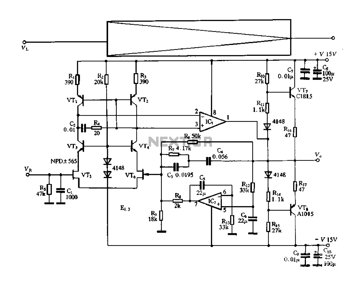
The electronic switch functions as a multifunctional preamplifier. It features a five-way touch electronic switch, a high-speed DC servo RIAA ultralow distortion amplifier, and can control volume, tone, and power amplifier electrical path phase. The TC9152, shown in Figure...
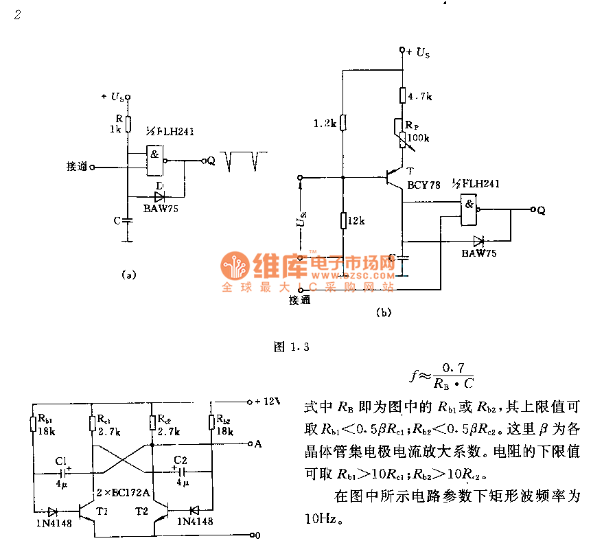
The circuit consists of two components whose parameters and models are designed to simultaneously generate a rectangular wave with a duty cycle of 1:1. The frequency is defined by the equation f = 0.7/(RB * C), where RB refers...
The circuit detects a sudden shadow falling on the light-sensor and sounds the bleeper when this happens. The circuit will not respond to gradual changes in brightness to avoid false alarms. The bleeper sounds for only a short time...
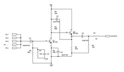
This circuit, referred to as an Audio Mixer, is a very simple design that utilizes easily obtainable components. Typically, audio mixer circuits require several integrated circuits (ICs); however, this particular audio mixer circuit relies solely on transistors as its...
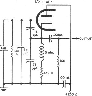
To update the fundamental oscillator circuits, simply replace the transistors with tubes. Alternatively, if one owns a vintage vacuum tube radio, it may be of interest to learn about historical practices. In general, the foundational principles of electronic circuits...
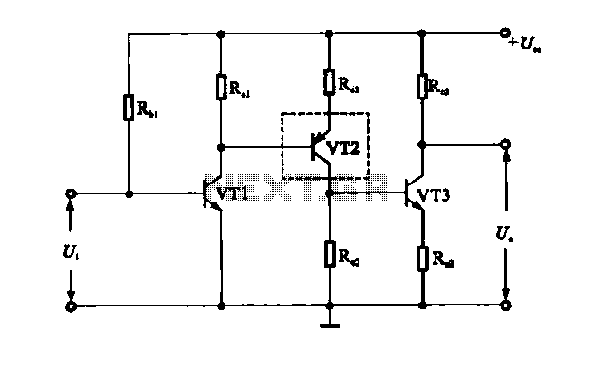
A multi-stage DC-coupled amplifier circuit utilizes NPN type transistors. Each stage is designed to achieve an appropriate operating point at the base, resulting in a stepwise increase in collector potential, which subsequently reduces the final output voltage range. To...