
Electronic switching preamplifier

The electronic switch circuit is designed to provide seamless integration of various audio sources while maintaining high fidelity and low distortion. The use of a five-way touch electronic switch allows for intuitive operation and reduces the wear and tear associated with traditional mechanical switches. The high-speed DC servo RIAA amplifier ensures that audio signals are amplified accurately, preserving the integrity of the sound.
The differential input circuit configuration, utilizing common source and common emitter arrangements, enhances the circuit's performance by minimizing noise and maximizing gain. The choice of the NPD5565 FET is particularly significant, given its low noise characteristics and high transconductance, which contribute to the overall audio quality.
The flexibility of the TC9152 allows it to operate across a wide voltage range, making it suitable for various applications. The inclusion of a DC servo circuit further enhances the stability of the amplifier, ensuring consistent performance over time. The phono equalizer network is critical for adapting the audio signals from different sources, ensuring that the output remains balanced and true to the original recordings.
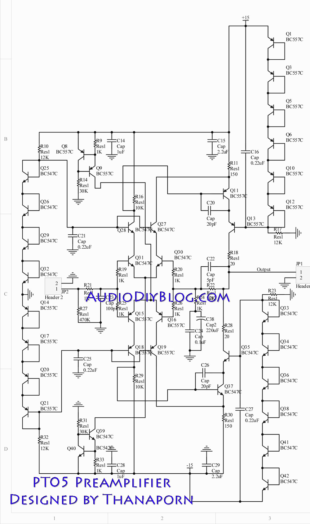
In summary, the electronic switch and preamplifier design provides a robust solution for audio signal management, combining advanced electronic components and thoughtful engineering to deliver high-quality audio performance in a versatile package.Electronic switch is a multifunctional preamplifier. It consists of five-way touch electronic switch, high-speed DC servo RIAA ultralow distortion amplifier. It can be volume, tone control circuit and power amp electrical path phase. Figure 3-24 is the TC9152. Composed Rd electronic touch switch. In Figure 3-23 VT3 ~ expansion upbraid composition common source - common emitter type differential input circuit, VTc, VT2 is mirroring the constant current source load. IC1 main amplifier, Vr7, VT8 push-pull output o IC2 composition DC servo circuit, Island, C6, Rl2, R13 DC servo time constant can be determined.
R, R, C3, C4 composition phono equalizer network., R9 DC feedback circuit path for DC gain adjustment. Circuit, the differential input FET to US production NPD5565 FET on the tube, is a low-noise high transconductance only on the tube, a withstand voltage of 55v-j aim is 10 ~ 30rnAr parameters can also be used, similar to the characteristics of a field effect should tube.
Audio switch uses Toshibas dedicated touch electronic audio analog switches (non-energy than conventional digital switches intended), to eliminate the impact of noise and poor contact phenomena arising from mechanical switch. 152 can be single, dual power under normal operation, the operating voltage range of 7.5 ~ 30V0 2412 feet respectively connected to the positive and negative power; 6 to 10 feet for the first L channel input to the fifth child switches; 18 ~ 14 feet for the first through fifth group R channel input switch; 1113 feet respectively, L, R channel output terminal; 23 to 19 feet were the first to fifth set of switches control terminal, where respectively FUNER ( tuner), CD (CD player), tAPE (tape recorder), AUX (auxiliary input), pHONO (record player), when one is a foot-high v + trigger corresponding L, R channel switch is turned on the other four open were closed off, while the output pin high, driving LED display working status, strong five foot drive capability, output current up to 20mA; 2 feet for the end of the function is disabled, then zero level, the switch control does not work 19 to 23 feet, through the positive power supply connected normally the case; 3 pin external Rx, Cx determines the clock frequency of the oscillation frequency by the formula fosc 1/1,5RxCr decisions generally take 20Hz ~ 100H, the oscillator starts to oscillate after entering the role, after five input clock pulse oscillator stop swing; 4 feet off the analog switch control terminal, usually then low, then high when, all of the analog switch is turned off, Lee may this pin can be more than just cut off the feet of four 152 in combination; 5 feet squelch control output, high output in the process of switching level for driving mute switch off the output signal (rate circuit is not used, so no mute function), squelch signal output by the oscillation frequency of the time table to determine: T startled feet 1/f 4 second; in addition, 23 to 19 feet with remote Control trigger signal conversion circuit also enables remote operation of the circuit .
Related Circuits
The next stage operates in conjunction with the first stage and is fully complementary. A cascode circuit is included to enhance the linearity of the amplifiers. This cascode circuit requires a constant reference voltage for biasing to activate the...
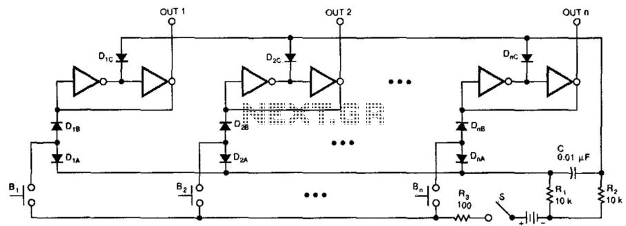
This switching circuit functions as a bank of interlocked mechanical switches. Activating one of the buttons latches its corresponding output while unlatching a previously selected output. A pair of inverters creates a latch for each output. For instance, pressing...
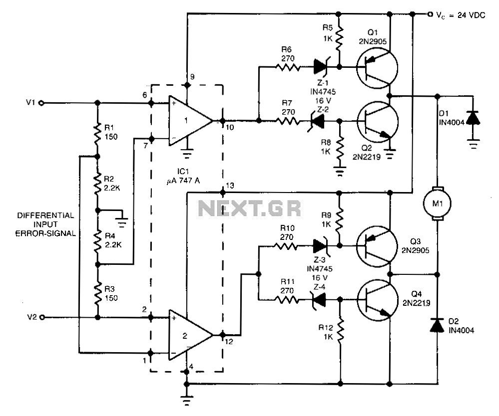
This high-performance switching controller for a low-power DC servo motor utilizes a symmetrical complementary-transistor bridge. The bridge functions as a reversing switch between the motor and a single-ended power supply. Because the transistors operate in a fully on or...
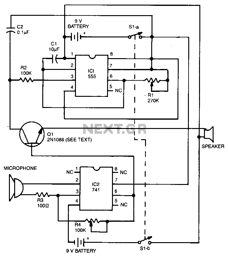
The 555 timer operates as a tone generator configured in astable mode. Its output at pin 3, which is a square wave, is converted into a triangle wave using resistor R1 and capacitor C2. The pitch of the generated...
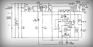
This is a low voltage, high-current output switching DC power supply with an input of 220 volts AC. In this circuit, an ST2 DIAC relaxation oscillator, Q3, C1, and the DIAC initiate conduction of the output switching transistor Q1....
The SL517 is designed as an audio, RF, or infrared decoder circuit suitable for electronic toy applications. The internal circuitry consists of an analog amplifier, a frequency divider, a bistable circuit, and a driver. It utilizes CMOS technology, has...