
12V Battery to 220V Power Inverter charge controller

The 12V power inverter circuit typically consists of several key components that work together to achieve the conversion from DC to AC. At its core, the inverter employs a switching mechanism, often utilizing transistors or MOSFETs, to rapidly switch the DC voltage on and off. This switching creates a square wave output, which can then be transformed into a sine wave using additional filtering and modulation techniques.
The circuit begins with a DC power source, commonly a 12V battery. This voltage is fed into an oscillator circuit, which generates a high-frequency signal. The oscillator can be implemented using a 555 timer IC or a microcontroller, depending on the desired complexity and features of the inverter.
Next, the output from the oscillator drives the gates of the transistors or MOSFETs. These components act as switches, turning on and off in response to the oscillator's signal. The switching creates a pulsed output, which is then passed through a transformer. The transformer serves two primary functions: it steps up the voltage to the desired AC level (typically 120V or 230V, depending on the application) and provides electrical isolation between the input and output.
After the transformer, the output may still exhibit a square wave form. To convert this square wave into a more usable sine wave, additional filtering components, such as capacitors and inductors, are employed. These components smooth out the output waveform, reducing harmonic distortion and improving the quality of the AC signal.
Finally, the output can be connected to standard AC loads, enabling the use of household appliances and other devices that require AC power. Safety features, such as fuses or circuit breakers, may also be incorporated into the design to protect against overloads and short circuits, ensuring reliable operation of the inverter.A power inverter converts DC power or direct current to standard AC power or alternating current. The following schematic shows a 12V power inverter Circuit Diagram. 🔗 External reference
Related Circuits
This regulated power supply is adjustable between a few volts and 15V using P1, while P2 is used to set the upper limit at 15.0V. The value of R6 is calculated as 0.7V divided by Imax, where Imax represents...

Sustainable satellite 802.11b wireless internetwork and how it was achieved. The design of a sustainable satellite 802.11b wireless internetwork involves the integration of satellite communication technology with wireless networking standards to create a robust and efficient communication system. This architecture...
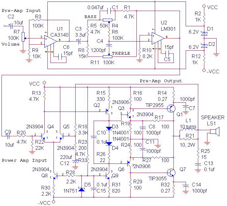
The circuit power amplifier depicted is a schematic design for a power amplifier with an output power of 70 watts, operating in Class AB mode. This power amplifier circuit is equipped with a tone control circuit. The 70-watt power...
This motor speed controller utilizes a single IC, the LM1014, to regulate the speed of a DC motor. It detects the increase in motor current as the rotation of the motor increases. The motor speed controller is designed around the...
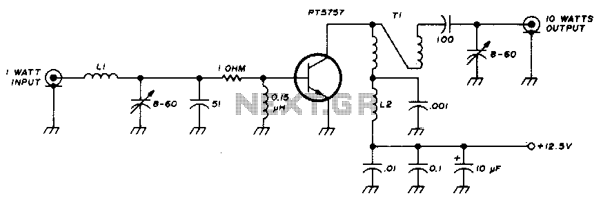
This 10-watt, 144-MHz power amplifier utilizes a TRW PT5757 transistor. The inductor LI consists of 4 turns of no. 20 enameled wire with a 3/32" inner diameter, while inductor L2 comprises 10 turns of no. 20 enameled wire with...
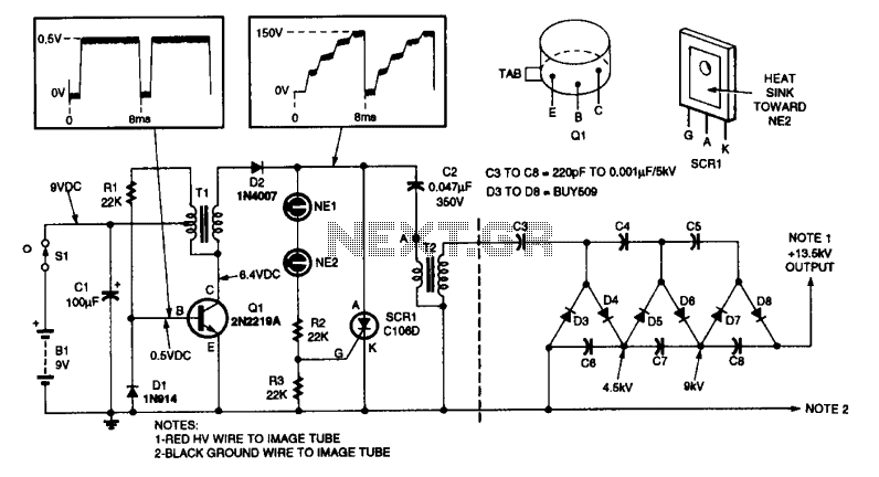
This high-voltage power supply features an inverter circuit centered around Q1, which generates 150-V pulses for the converter SCR1 and capacitor C2. The output from component ?2 produces a 4.5-kV pulse, which is further amplified by a voltage-tripler network...